Now i am very pleased with the crossover setup,but without measured the speaker.
But simulated crossover in xsim is not same as reality,i notised that right now.
Is someone having a setup like this?
Dayton rs1504p and Seas h1396 setup,and having some of there own crossover suggestions of this diy project...
But simulated crossover in xsim is not same as reality,i notised that right now.
Is someone having a setup like this?
Dayton rs1504p and Seas h1396 setup,and having some of there own crossover suggestions of this diy project...
Attachments
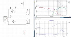
Averaging 2Ω impedance across so much of the spectrum will tax a lot of amplifiers - make sure you're using one that's happy with such a low value, or redesign for a higher average impedance.
Actually, just noticed what's causing that - L2 should be after (ie on the driver side of) C2, not before it.
Also, I think you've got more shaping than I'd want to see at this stage - the slope down from LF through the mids might be OK if it is to compensate for bafflestep, but I think the rise from 2kHz to 15kHz is probably too much - it might sound nice at first, but would be better long term if flatter.
Averaging 2Ω impedance across so much of the spectrum will tax a lot of amplifiers - make sure you're using one that's happy with such a low value, or redesign for a higher average impedance.
Actually, just noticed what's causing that - L2 should be after (ie on the driver side of) C2, not before it.
Also, I think you've got more shaping than I'd want to see at this stage - the slope down from LF through the mids might be OK if it is to compensate for bafflestep, but I think the rise from 2kHz to 15kHz is probably too much - it might sound nice at first, but would be better long term if flatter.
Yes,the impedance vent very bad,want is your thought about this mew idea?
Attachments
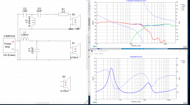
Looks better to me.
It's worth turning on the phase trace for each drivers curve in the response graph to check they're pretty close too. Of course, if the two FRD files have not had their measurements taken in exactly the same way (eg mic distance from baffle) then any phase/timing info extracted from them will be at best approximate, but it's probably still worth doing.
It's worth turning on the phase trace for each drivers curve in the response graph to check they're pretty close too. Of course, if the two FRD files have not had their measurements taken in exactly the same way (eg mic distance from baffle) then any phase/timing info extracted from them will be at best approximate, but it's probably still worth doing.
Looks better to me.
It's worth turning on the phase trace for each drivers curve in the response graph to check they're pretty close too. Of course, if the two FRD files have not had their measurements taken in exactly the same way (eg mic distance from baffle) then any phase/timing info extracted from them will be at best approximate, but it's probably still worth doing.
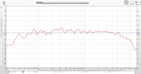
I have done a measurement with this setup!
thoughts about this
Attachments
- Status
- Not open for further replies.