d appolito configuration
hi ,
can any body tell me what is d appolito configuration of placing a tweeter betwean two midrange is all about ?
how does it improve the sonic quality , can it be used in an active system of 3 way design ?
regards ,
somak

hi ,
can any body tell me what is d appolito configuration of placing a tweeter betwean two midrange is all about ?
how does it improve the sonic quality , can it be used in an active system of 3 way design ?
regards ,
somak
That's a good question. I've been using that config for years, but recently I start to doubt if it really that good. Simple TM arrangement might actually sound better.
Anybody with more info on that subject?😉
Anybody with more info on that subject?😉
has to do with keeping the the lobing effect of the radiation pattern, and tring to keep it symetrical.
It has come to mean "symmetrical MTM," though that configuration well predated d'Appolito's fist published paper on the subject. IIRC, some speakers designed for Koss by Ashley in the '70s used this arrangement.
Originally, d'Appolito specified the MTM arrangement with an odd-order crossover (usually 3rd order) to smooth out lobing. In more recent years, he's gone over to using 4th order Linkwitz-Reilly. In any event, the symmetry of the arrangement guarantees symmetry of the vertical polar pattern. Whether that's a good or a bad thing depends on the design goals.
Originally, d'Appolito specified the MTM arrangement with an odd-order crossover (usually 3rd order) to smooth out lobing. In more recent years, he's gone over to using 4th order Linkwitz-Reilly. In any event, the symmetry of the arrangement guarantees symmetry of the vertical polar pattern. Whether that's a good or a bad thing depends on the design goals.
ds21 said:has to do with keeping the the lobing effect of the radiation pattern, and tring to keep it symetrical.
Better yet is to mount the tweeter co-axially (often not very convienient thou)
SY said:It has come to mean "symmetrical MTM," though that configuration well predated d'Appolito's fist published paper on the subject. IIRC, some speakers designed for Koss by Ashley in the '70s used this arrangement.
I built my 1st MTM in 1975. They used 2 8" drivers -- the very 1st of the clear poly drivers -- service spares from Harbeth IIRC.
In an MTM i like to get the drivers as close together as possible, and i usually offset the tweeter into the V of the 2 main drivers. With 2 midbasses i will do a bi-pole before i do an MTM, but i am trying to find a suitable tweeter for a bi-pole MTM, whose primary purpose is to get more of my alnico 4" into the same enclosure & push the efficiency up.
dave
Better yet is to mount the tweeter co-axially (often not very convienient thou)
Not to mention the diffraction problems that this inevitably causes.
SY said:Not to mention the diffraction problems that this inevitably causes.
I think you are imagining a different config them i am. I was thinking of the small tweeter pearched on the phase plug -- like the PHY-HP.
An externally hosted image should be here but it was not working when we last tested it.
Requires a tweeter with a small footprint and a driver with a largish voice coil.
dave
Yeah, I've played with those sorts of drivers (even built one with an LPG minitweeter); there's always, IME, a severe compromise with the polar pattern, especially at high frequencies.
Hey, this post is 1,000 for me!
BTW, you are now officially my wife's Most Hated Person.
Hey, this post is 1,000 for me!
BTW, you are now officially my wife's Most Hated Person.
Attachments
SY said:Hey, this post is 1,000 for me!
congrats
BTW, you are now officially my wife's Most Hated Person.
🙂
Those do look familiar. I like that the stand is a bit wider, that should help the lower mid dipole cancelation a little tiny bit -- some day i'd like to hear a set mounted in the wall using the room on the other side as enclosure.
Are you using them with a woofer?
dave
Actually, the stand is going to nearly triple in width by the time I'm done. Right now, we're just in Phase I ("Collect Underpants!"). I'll fire the subwoofers back up in a week or two; I want to get a better handle on what the ESLs are doing before I redo the crossover to the woofers. A line source of 15 or so 5" drivers per side, used as dipoles and integrated into the baffle, is in the works. One fun thing was redoing some of the conductive traces on the diaphragms without disassembling the stators.
I've got the first iteration of the direct drive amp sorted out- the input stage, which simulates the response of the summed transformer drive, is completed (in breadboard format). The hard part (output stage) is next.
Sorry for the minor hijack of the thread.
I've got the first iteration of the direct drive amp sorted out- the input stage, which simulates the response of the summed transformer drive, is completed (in breadboard format). The hard part (output stage) is next.
Sorry for the minor hijack of the thread.
SY said:Sorry for the minor hijack of the thread.
You just need to squeeze a little ribbon in there between the 2 panels and you have an MTM -- see not off topic at all 🙂
dave
planet10 said:
With 2 midbasses i will do a bi-pole before i do an MTM
How would you approach that, as push pull or or two separate enclosures with drivers in front and back? I'm thinking about similar project and frankly, MTM doesn't appeal to me anymore. Especially, when I'm using only than 1st order crossovers.
Peter Daniel said:How would you approach that, as push pull or or two separate enclosures with drivers in front and back? I'm thinking about similar project and frankly, MTM doesn't appeal to me anymore. Especially, when I'm using only than 1st order crossovers. [/
Here is a drawing of a bipolar centre channel we are just finishing up -- the tweeter is not shown. The drivers are not shielded so the magnet-to-magnet configuration is a contraint on the design -- as an ML-TL so are the length & the cross-section. This is one of the reasons the drivers are mounted from behind the baffle.
Magnet-to-magnet is ideal in terms of maximizing the push-push effect but other considerations will often mean you have to connect the magnets with an intervening piece of hard-wood or metal (anyone want to bet on the use of Al if PD goes this route?). A common cabinet is preferred -- gives the drivers more distance before 1st reflections get back to the cone.
The big advantages are the push-push effect & no bafflestep. The "disadvantage" is that the back of the speaker has to be out into the room -- depending on the room you may or may-not roll-off the back driver at or slightly above the BS frequency.
dave
Attachments
PS: the progenitor of my move towards push-push bi-poles is the TLb.
dave
An externally hosted image should be here but it was not working when we last tested it.
dave
planet10 said:
You just need to squeeze a little ribbon in there between the 2 panels and you have an MTM -- see not off topic at all 🙂
dave
Dave: I tried that, but I don't know that it really improved the sound.
Attachments
SY said:I tried that, but I don't know that it really improved the sound.
LOLROF 😱
dave
By push-push you mean that drivers are connected in phase and move in opposite direction so the enclosure is more pressurised?
I am actually thinking about mounting drivers in the wall, using the room on the other side as enclosure. Is there a way to use that bi-pole setup in this case?
I am actually thinking about mounting drivers in the wall, using the room on the other side as enclosure. Is there a way to use that bi-pole setup in this case?
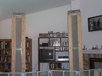
I showed these pics to my wife
all of a sudden I don't seem so bad... thanks
Always happy to assist. The nice carpenter-built frames will come along when my wife gets her next raise. 😉
Do they work? Yep. A bit of panel refurbishment here and there, some rewiring of the transformer boxes, a few blow-ups as I learned how to measure the frequency response of the electrical signal applied to the panels, and a good idea but a practical dead end for the frame design... anyway, the temporary lash-up sounds pretty good.
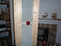
The fence does no good against our five cats, but effectively keeps my 2-year-old's fingers off the diaphragms. The cats learned day one, the hard way, to give these a wide berth. My kid is somewhat stupider than my cats and needs protection.
- Status
- Not open for further replies.
- Home
- Loudspeakers
- Multi-Way
- d'Appolito configuration