Does anyone have a schematic for a Danelectro model 78?
It looks to be all original. Has the two prong cord.
I didn’t plug it in.
It looks to be all original. Has the two prong cord.
I didn’t plug it in.
Last edited:
Here are some photos.
Attachments
-
 9AE9D34B-FB36-4AFE-957F-26FE039D5DA8.jpeg812.9 KB · Views: 145
 -
 126AD733-F2D1-4D7B-B697-5F2F6D0F8FFE.jpg518.1 KB · Views: 155
 -
 D9E523F2-1990-4FDC-AA4C-92C43AFCB2BD.jpg612.5 KB · Views: 144
 -
 53DB6D96-335C-4633-9AD5-4E0BC67B2954.jpg806.7 KB · Views: 147
 -
 F82A7A29-B833-40DF-96EC-A8763A892DA4.jpg831.7 KB · Views: 147
Last edited:
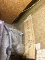
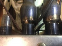
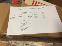
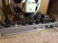
Interesting your sample has a paper slip showing four 6V6 but actually has two very old 6L6G. It is 20-30 watts either way, and Dan could have swayed with prevailing price 6V6 vs 6L6, but he'd print up a new slip, no?
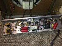
What's really there "should" be obvious. These are not PCB SMD micro-miracles. They are not even fancy circuits, though the split between top and bottom units is confusing at first.
Do you know how to reduce risk of shock and fire at first- smoke-test? I would probably clear the mouse and spider corpses first.
I was scratching my head too. The sample paper has eight tubes but I only see seven. So far. Looking forward to opening it up. I need to make a chicken stick.
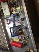
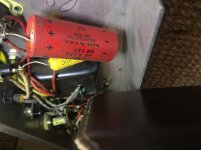
This is truly fun. When I inspected the underbelly of this chassis it looked to be all original.
Then I noticed Planet capacitors (1970’s era replacements) and a Sprague cap with a date code that looks like 1968.
This led me to think the bottom chassis was swapped out in the early 70’s. But when I opened up to upper chassis there are hand written initials that match the bottom chassis.
The mismatch between the paper tag and what is actually in this amp has me perplexed.
My best guess is this amp was serviced by an extremely competent person in the 70’s. The solder joints look undisturbed.
There is a burnt out resistor that may have been caused by a shorted out out tube.
(Circled in blue)
Pics are on the way
More pics
Attachments
-
 327F6C93-69E5-4000-BAFB-C464DAD3183B.jpeg637 KB · Views: 93
 -
 934C29FA-79DA-46BA-B439-E13569DB9DFC.jpg587.5 KB · Views: 88
 -
 62435D8D-E246-4AE3-AE38-ACA359922CFC.jpg556.8 KB · Views: 81
 -
 F9A44D1D-813A-4604-A0ED-07C318F5EB46.jpg727.7 KB · Views: 90
 -
 386980B3-EF15-48F0-BBAE-4C584B620990.jpg738.4 KB · Views: 100
Last edited:
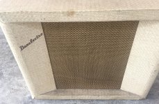
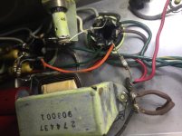
If your speaker and the underside transformer are original, the date code is 1954. Can't find anything except a few pictures.
I tested all of the tubes except the two 12AX7 tubes (my tester is too old)and they all passed.
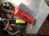
Here is a better shot of the burned resistor. It’s connected to pin 4 of V6 (G2).
Here is a better shot of the burned resistor. It’s connected to pin 4 of V6 (G2).
Attachments

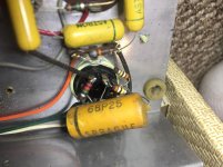
That's a dropping resistor for the screen supply, which then goes on to feed downstream power supply nodes. Also looks like it was only a 1/4W, which is way too small for what it's feeding. (By comparison, Fender used 1W screen resistors, and that was with one per tube, albeit at higher voltages than those 6L6Gs would be using).
The model 89 schematic has a paralleled pair of 4.7k, probably to handle higher power. It's possible that they were replaced during earlier repairs with a single under-spec resistor.
If it were me, I would replace it with the same thing, but uprated - two paralleled 4.7K 1W resistors. Since it's impossible to tell what value got burned out, and those 6L6G screens can only take 270V, maybe start by clipping in a single 4.7k and measuring the screen voltages before going down in value.
(If it were me, and it was my amp, I would actually rework that bit of the power supply to branch off the screen supply and give each tube its own screen resistor. But that's venturing into mod territory and might change the sound.)
Thank You deafen.
I soldered in two 4.7K 1 W resistors. Now the amp works. It has great tone too. But. It does have a bit of noise. While warming up it buzzes and when it warms up enough to hear the guitar the buzz / hums is less noticeable. The reverb is not so good. it sounds like a bull frog out in the distance. made me laugh. I am actually it works at all with the old capacitors. All in all I am very pleased.
Thanks everyone for helping.
WHICH reverb???? 😕The reverb is not so good. it sounds like a bull frog out in the distance. made me laugh.
Hola JMFahey, tienes un ojo atento.
(I hope my Castellano is readable, after 30 years...)
Indeed, no reverb on that amp.
(I hope my Castellano is readable, after 30 years...)
Indeed, no reverb on that amp.
😀Hola JMFahey, tienes un ojo atento.
(I hope my Castellano is readable, after 30 years...)
Indeed, no reverb on that amp.
😀Ritchie C I meant vibrato
- Home
- Live Sound
- Instruments and Amps
- Danelectro Maestro Mod. 78 Series D