This is cool....
Very cool!
Only primary effects are omitted completely.
Second try, man that excel beat me up...
Here is the basis for my discussion of damping factor vs quadrant of operation.
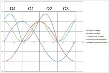
The time graphs are all normalized with +/- 1 as levels, the timebase is 360 degrees wide.
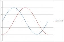
First is a time diagram of an inductor driven by AC. We all know ELI the ICE man, note that the voltage (E) leads current (I). Note that this is a steady state representation, NOT starting at zero, but continuing through zero.
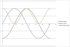
The second shows the energy storage within the inductor. The energy within an inductor is E = 1/2 L I(squared), so shows as twice the frequency (note that I simply squared the current, so energy only goes to 1 max, current and frequency are scaled accordingly with relevant L and F included.) The nature of the beast is that the energy returns to the line when it is driven off the wall socket for example. A power supply transformer does exactly this, and one will find that there is current driving it. Note also that EMF is driving the energy back into line from the inductance, non linearity is NOT required for EMF.
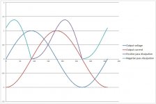
The third shows the pass element dissipation as a consequence of an inductive load. I normalized the rail voltage to 1.1 as a reasonable guess. I separated out the plus and minus pass elements as light blue and violet. When current is positive, the positive pass elements are the ones supporting it, and neg current requires the negative pass elements. Note the two dissipation lobes are zero when the current passes through zero. Note also that the dissipation is maximum at a point that is not concurrent with maximum voltage OR maximum current.
The fourth puts all the curves together. Quadrants have been labelled, see below... Of note here is the fact that maximum pass element dissipation occurs during the discharge of the inductive storage. We spoke a bit of this earlier, in that the amp dissipates in trying to keep the output node at zero, and the load is responsible for dissipation of it's own stored energy. Since this is a graph depiction of an inductor with no resistance, no consideration of the load dissipation has been included.
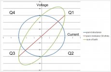
The fifth is the VI graph. The blue is a pure inductance, the red is a pure resistance, and the green is the sum of the two.
I also labelled the quadrants (be careful, I changed the numbering to CW increase from 1 to 4, I previously went CCW in my last description. This direction (CW numbering) will be the convention I use from now on.
edit: The question becomes: is the damping factor as measured through the origin with current driven signals the same as measured anywhere along the red resistive line? And, is it the same if measured anywhere along the ellipse cause when reactance is included as part of the load?
John
Here is the basis for my discussion of damping factor vs quadrant of operation.
The time graphs are all normalized with +/- 1 as levels, the timebase is 360 degrees wide.
First is a time diagram of an inductor driven by AC. We all know ELI the ICE man, note that the voltage (E) leads current (I). Note that this is a steady state representation, NOT starting at zero, but continuing through zero.
The second shows the energy storage within the inductor. The energy within an inductor is E = 1/2 L I(squared), so shows as twice the frequency (note that I simply squared the current, so energy only goes to 1 max, current and frequency are scaled accordingly with relevant L and F included.) The nature of the beast is that the energy returns to the line when it is driven off the wall socket for example. A power supply transformer does exactly this, and one will find that there is current driving it. Note also that EMF is driving the energy back into line from the inductance, non linearity is NOT required for EMF.
The third shows the pass element dissipation as a consequence of an inductive load. I normalized the rail voltage to 1.1 as a reasonable guess. I separated out the plus and minus pass elements as light blue and violet. When current is positive, the positive pass elements are the ones supporting it, and neg current requires the negative pass elements. Note the two dissipation lobes are zero when the current passes through zero. Note also that the dissipation is maximum at a point that is not concurrent with maximum voltage OR maximum current.
The fourth puts all the curves together. Quadrants have been labelled, see below... Of note here is the fact that maximum pass element dissipation occurs during the discharge of the inductive storage. We spoke a bit of this earlier, in that the amp dissipates in trying to keep the output node at zero, and the load is responsible for dissipation of it's own stored energy. Since this is a graph depiction of an inductor with no resistance, no consideration of the load dissipation has been included.
The fifth is the VI graph. The blue is a pure inductance, the red is a pure resistance, and the green is the sum of the two.
I also labelled the quadrants (be careful, I changed the numbering to CW increase from 1 to 4, I previously went CCW in my last description. This direction (CW numbering) will be the convention I use from now on.
edit: The question becomes: is the damping factor as measured through the origin with current driven signals the same as measured anywhere along the red resistive line? And, is it the same if measured anywhere along the ellipse cause when reactance is included as part of the load?
John
Attachments
Last edited:
John, I need some time to digest it, but shooting from the hip (assuming I even understand your question) I would say that the damping factor would vary in those cases.
Working from the definition of load impedance over source impedance, as load impedance varies both in magnitude and angle, so would the damping factor. I think.
Jan
Working from the definition of load impedance over source impedance, as load impedance varies both in magnitude and angle, so would the damping factor. I think.
Jan
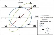
Here is the VI graph with several points of interest attached.
Damping factor is measured by forcing current into the output node and measuring the resultant voltage deviation.
At point A, the amp is on but quiet.
B; the amp is pushing into a resistive load, and is then prodded with the measurement current. This can be forcing the amp with a DC signal, or using a LF drive with the damping drive at a second higher frequency, perhaps consistent with a midrange frequency.
C is measured when the output voltage is maximum yet the output current is zero.
D is somewhere in the middle of reactive region, somewhere near maximum pass element dissipation.
E is peak VI product in the resistive quadrant.
I am unaware of any damping factor discussion or test which considers these entities, there may be some out there.. However, to assume that the damping factor everywhere in the VI space being exercised is the same, well I've not seen anything to support that assertion.
And yet, the midrange cone of a two or three way system is relying on the damping factor being stable everywhere along the green line that the woofer is forcing the amp to follow..
John
Attachments
Last edited:
I am unaware of any damping factor discussion or test which considers these entities, there may be some out there.. However, to assume that the damping factor everywhere in the VI space being exercised is the same, well I've not seen anything to support that assertion.
I've never seen an attempt to define DF with complex quantities, care to suggest one? The output impedance of the amplifier in the general case is complex as well as varying with instantaneous I and V.
I've never seen an attempt to define DF with complex quantities, care to suggest one? The output impedance of the amplifier in the general case is complex as well as varying with instantaneous I and V.
As a first pass, I'd try for a resistive one superimposed on a complex output signal.
Set the amp output at some DC value. In the prev pic, set the output at -22 volts. (location "D")
Push or pull current from the output node with a current sink. In the example pic, pull the out towards the negative rail with 2 amperes. (not to ground, that's just what everybody would expect..)
Drive a hf signal into the output node with a current controlled device.
Measure the hi freq amplitude of the output voltage ripple. As well, spectra of that ripple may prove interesting (or, it may not)..
By varying the DC out and the current pulled, one can test the entire amplifier output space.
Of course, ya hafta use realistic numbers for the amplifier being tested. My pic uses 50 volt rails, pulling 2 amperes with an output setpoint of -22 volts will drop 144 watts dissipation into the positive pass devices..
John
Last edited:
Intuitively I thought that as the impedance of the driver rises at resonance, the drive current would go down for the same motion/speed. So the EMF would stay up (because the motion continues in my simplistic view) with the drive going down.
Jan
I wanted to elaborate on a point a tad.
A simplistic measurement of a speaker impedance such as the stereophile has some misconceptions that need to be addressed.
A speaker which couples to the air using a resonant mechanism (pretty much everything except horns) does NOT present the measured impedance at the initiation of the signal. For example, if I were to gate a sine wave into a 4th order bandpass, the measured steady state SPL will NOT be there at the first cycle or two, or three. Because it is a converter with several storage mechanisms, that storage has to build up over some cycles.
As a result, the impedance that is actually presented to the amp for first cycle will be significantly different. As time goes on, the impedance will converge to the measured steady state value.
At the end of the signal, the system also cannot simply shut off, it will decay at the resonant frequency. If the amp is being demanded to shut it down, the back EMF of the storage mechanism will push the output node despite the amplifier signal being significantly less (or even quiet).
If a gated LF were driven into a speaker near resonance, the buildup of resonance will be spotted by the modulation of the VI curve, the ellipse will rapidly morph from the instantaneous impedance to the steady state one. When the signal is shutoff, the ellipse will go flat and the decay will be lost in the roughly horizontal line (assuming current is the horizontal axis.
I note Peter Baxandal had voltage horiz, figures...I tossed over the choice earlier, but decided to stick with current horizontal unlike the 576's I used back in the day..
John
Last edited:
A speaker which couples to the air using a resonant mechanism (pretty much everything except horns) does NOT present the measured impedance at the initiation of the signal. For example, if I were to gate a sine wave into a 4th order bandpass, the measured steady state SPL will NOT be there at the first cycle or two, or three. Because it is a converter with several storage mechanisms, that storage has to build up over some cycles.
As a result, the impedance that is actually presented to the amp for first cycle will be significantly different. As time goes on, the impedance will converge to the measured steady state value.
Don't you mean to say does NOT present the simplistic measured impedance?
I have to think about this, take the standard cone in a box electro-mecanical model in the differential equation form there are no time varying terms so this should yield an impedance for t>0 for any stimulus.
Well, yah.. The steady state measurement of a system at or near resonance is not the same at the time dependent impedance for a gated stimulus.Don't you mean to say does NOT present the simplistic measured impedance?
I have to think about this, take the standard cone in a box electro-mecanical model in the differential equation form there are no time varying terms so this should yield an impedance for t>0 for any stimulus.
I didn't say the math was easy, specifically differentials with gated functions.
Think of a pendulum. The amp said full swing NOW, not later..
John
Edit: There's a special place in "you know where" for simulation software designers who create product which is nefariously incorrect when gated complex signals are used to drive models. It's bad enough worrying about GIGO without being concerned about the accuracy of the software for transient behaviour. Granted, I can accept the complexity of the problem, but that doesn't sooth my nerves like a martini.. Perhaps it's better now (a decade later). I cringe at making another simulator, I'm getting too old for that..
Last edited:
I've never seen an attempt to define DF with complex quantities, care to suggest one? The output impedance of the amplifier in the general case is complex as well as varying with instantaneous I and V.
Years ago, Peter Walker wrote the output impedance of his amplifier in terms of an inductance in series with a resistance. So, complex damping factor was implicite, I presume... But remains a 1st order approximation.
Pierre
Last edited:
I didn't say the math was easy, specifically differentials with gated functions.
I know what we are missing, a transmission line analogy. 😀 It looks like the characteristic impedance for t<=2l/c for air and you don't "see" the steady state gamma/impedance until the electrical/magnetic energy and standing waves have built up to their equilibrium values.
One could certainly argue that the concept of DF outside of steady state sin wave stimulus is meaningless. You simply have a complex system with a transient response that varies with amplifier output Z. Staying linear and time invariant (which at the detail level is not exactly true) one would determine the other.
the "interface intermodulation distortion" was brought up as yet another hypothesis why high feedback factor amps "sound bad"
the usual suspects did the usual debunking job in the JAES 30 years ago
CordellAudio.com - Interface Intermodulation Distortion
smooth low order nonlinearity can be modeled well with low order Volterra if there were any reason to go beyond the simple relations
the usual suspects did the usual debunking job in the JAES 30 years ago
CordellAudio.com - Interface Intermodulation Distortion
smooth low order nonlinearity can be modeled well with low order Volterra if there were any reason to go beyond the simple relations
Awww.. Give it up! people babbling about what they have inadequate grasp of.
DF is a Meaningless number. Brochure babble nonsense...Let it go!
No-one is impressed with your personal claims/guesses/theories 🙄
Borrring... is an accurate descriptor for this Topic
DF is a Meaningless number. Brochure babble nonsense...Let it go!
No-one is impressed with your personal claims/guesses/theories 🙄
Borrring... is an accurate descriptor for this Topic
I know what we are missing, a transmission line analogy. 😀
Do NOT get me started. 😀
btw, you've no idea how that analogy has carried.. The guys in brazil (new light source with very fast beam position feedback) now understand the issue of cables, load impedance, and settling time when it comes to designing their system. They are making a fourth generation synchrotron light source, and need even better positioning control than we do. It was funny, asking them how far their fast corrector magnets were from the amplifiers, and what characteristic impedance they intended on using for the magnet runs..and seeing their faces...😱 One of the presenters actually took control system theory back in the "day"...his day being 2 decades after my "day"..sigh He actually understood what settling time was within the context of the discussion!!!...what is this world coming to???
Pretty much, if nobody's characterized it. If it means anything, it's in the realm of Arthur Clark's description of not understood science.One could certainly argue that the concept of DF outside of steady state sin wave stimulus is meaningless.
What is interesting is Arny's inclusion of speaker response curves as presented by stereophile. Steady state response, while good to know, does not actually show how a speaker will react to transients of actual music. The kick drum with it's very fast attack and decay comes to mind. When I run PA, I must admit that I really loved the horns, and hated the reflex. Even though I can now carry kilowatts of bass power, I still prefer the attack that non high order cabinets provide. I'm getting too old to carry all this stuff..
the "interface intermodulation distortion" was brought up as yet another hypothesis why high feedback factor amps "sound bad"
the usual suspects did the usual debunking job in the JAES 30 years ago
Hmm. well, thanks for the paper, it is interesting, if somewhat meaningless to the discussion.
It's amazing to see simulations of an arbitrary model of a totally linear system having nothing in common with reality, used in debunking reality.
You've seen what I've discussed, you understand what I've said, how I've tested in the past, what the theory is. But yet you've presented an entirely different paper with the belief that it "covers" the discussion. I do not agree with you.
The damping factor may indeed be totally linear w/r to the entire V/I space in agreement with linear models consistent with Cordell's thinking. The paper you provided however, does not prove so. I cringe at small signal approximations and models being used to cover high level power electronics...especially high level electronics that are not linearly symmetrical as class b power circuits tend to be.
Let's talk hardware. Build something, prove that the damping factor is truly independent of the load reactance, across the audible band. I've provided sufficient information to do so, I hope that somebody actually does it.
Regardless of your results, whether I am right or wrong, the information will prove valuable to others w/r to output protection schemes, speaker multiway number (2,3,4), speaker order (2,4,6,) and foldback protection boundaries.. We all gain from this discussion. Thanks for what you provide.
I read your post several times. Strangely, I found absolutely no relevant information. If all you intend to do is troll, please move on. We are having an actual technical discussion. You are welcome to join in if you have anything of value to add.Awww.. Give it up! people babbling about what they have inadequate grasp of.
DF is a Meaningless number. Brochure babble nonsense...Let it go!
No-one is impressed with your personal claims/guesses/theories 🙄
Borrring... is an accurate descriptor for this Topic
As to "inadequate grasp".. You've no idea the level of the people having this discussion, do you? You've a bit to learn. Please, do not act as a clown. If you've technical input to provide, do so.
John
Last edited:
you do see what is needed with the small signal Zout formulas when output Q gm dependency on Iout is included in the formula
with the now common recommendation for ~100 mA per output Q bias, AB stage |Zout| can be usefully bounded by the equations
with the now common recommendation for ~100 mA per output Q bias, AB stage |Zout| can be usefully bounded by the equations
As a result, the impedance that is actually presented to the amp for first cycle will be significantly different. As time goes on, the impedance will converge to the measured steady state value.
John
... which will then still be of the form a + j.b I guess.
Jan
you do see what is needed with the small signal Zout formulas when output Q gm dependency on Iout is included in the formula
with the now common recommendation for ~100 mA per output Q bias, AB stage |Zout| can be usefully bounded by the equations
No matter what terms are included within the model, the question always has to be: has the amplifier been designed so that linearity remains throughout the VI space it is being required to operate in. Are all the elements being treated nicely, remaining out of saturation and starvation. As a simple example, can an emitter follower properly drive a reactive load through a 4 quadrant VI space?
Is the amp designed for the steady state speaker impedance, or is it designed with sufficient overhead for the transient load. Is it even designed to handle the VI demands caused by 3 parallel reactive loads, each with their own VI demands vs frequency.
This thread is titled Damping factor explained - or not. As you can see, true damping factor is not just measured through the origin. The load upon the amp never goes through the origin during musical reproduction..(well, not on purpose..the VI plot "cloud" will in essence be everywhere during music.) Single notes at a driver's resonance are also not really what I listen to in music.
Which reminds me of the guy searching for his keys at the lightpost, despite having lost them in the darkness far away. Yes, we can test damping through the origin simply enough, but is it sufficient to describe the system behaviour?
... which will then still be of the form a + j.b I guess.
Jan
I would also assume that as well. We of course neglect all the really nasty-to-simulate second order plus effects, those would just muck up the discussion being had with little added value.
John
Last edited:
John you mentioned the emitter follower - if we consider an EF output stage, then each EF only has to operate linearly in two quadrants, right? I mean there's the little detail of crossover, but aside of that.
Jan
Jan
- Home
- Amplifiers
- Solid State
- Damping factor explained - or not?