Is it possible to damage a microphone transducer/membrane so it creates a resonace at 32/64/128hz? 🙈😝
neither of these boxes have that in their internal dimensions/design.
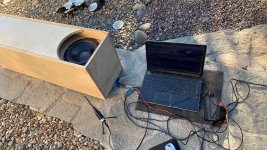
orange is a 40 hz tuned folded bose wave cannon (240 and 80 cm lengths) with a stepped expansion
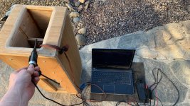
green is a 24 hz taped tapered tube… with a stepped reduction
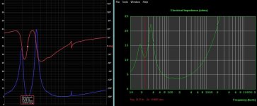
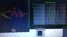
the measured impedance plots verify/match the horn response design
neither of these boxes have that in their internal dimensions/design.
orange is a 40 hz tuned folded bose wave cannon (240 and 80 cm lengths) with a stepped expansion
green is a 24 hz taped tapered tube… with a stepped reduction
the measured impedance plots verify/match the horn response design
Attachments
No.Is it possible to damage a microphone transducer/membrane so it creates a resonace at 32/64/128hz? 🙈😝
I owned a 1/4" RTA mic that the element receded into the housing by about 1/4" and it created a 12kHz peak in it's response, but that's not in the sub range 😉
Neither the orange or green frequency response traces in the OP or the red and blue in post #3 appear to have octave based resonance peaks or dips.neither of these boxes have that in their internal dimensions/design.
The impedance plots look like they might be octave based (not at the integers of 32/64/128..), if they verify/match the horn response design the question would be why the frequency response trace peaks don't match.
Your mic placement in the OP looks random, so can't comment much on the frequency response traces 😎
Ok, thanks on clearing up the potential microphone issue 🙏🏻
i just held the microphone @ the vent in each. I thought the 32 hz was a room mode but I remeasured outside and it was still there
i just held the microphone @ the vent in each. I thought the 32 hz was a room mode but I remeasured outside and it was still there


