Are ceramics polarised?
Looks like doesn't matter which way round they are used
Can someone clarify please
Looks like doesn't matter which way round they are used
Can someone clarify please
I see pins 4 and 8 that i am to take to ground with the ceramics are v- and v+
Can i ask a question... where is the best place to take those to ground in the dacmagic1?
Don't want any silly mistakes at this stage 🙂
Thanks
Can i ask a question... where is the best place to take those to ground in the dacmagic1?
Don't want any silly mistakes at this stage 🙂
Thanks
"Try some extra 0.1uF decoupling on each OpAmps power rails. Pin 4 to GND and pin 8 to GND."
Could anyone advise where i should take ground from.
Thanks
Could anyone advise where i should take ground from.
Thanks
Theoretically, the best ground should be closest to the output side of the OpAmp (the ground closest to the side with pins 1 and 7).
So best way to determine which one to use would be with a multimeter on continuity?
One probe on the casing, and find the closest GND point to either side of the opamps. (ie on a resistor, or cap next to the opamps) And solder a ceramic onto the closest gnd on each side?
One probe on the casing, and find the closest GND point to either side of the opamps. (ie on a resistor, or cap next to the opamps) And solder a ceramic onto the closest gnd on each side?
What casing? Measuring what? Ground resistance?
Nono, just eyball it... Can't you see the ground on PCB?
Nono, just eyball it... Can't you see the ground on PCB?
No gnd markings on the pcb anywhere.
I seen on the internet that measuring continuity between one of the pcb fixing screws , and solders nearby the opamps i would be able to beep out a gnd.
Am i mistaken with this, is there a better way to find a gnd point if you dont have the schematic?
I seen on the internet that measuring continuity between one of the pcb fixing screws , and solders nearby the opamps i would be able to beep out a gnd.
Am i mistaken with this, is there a better way to find a gnd point if you dont have the schematic?
Bump
No gnd markings on the pcb anywhere.
I seen on the internet that measuring continuity between one of the pcb fixing screws , and solders nearby the opamps i would be able to beep out a gnd.
Am i mistaken with this, is there a better way to find a gnd point if you dont have the schematic?
No gnd markings on the pcb anywhere.
I seen on the internet that measuring continuity between one of the pcb fixing screws , and solders nearby the opamps i would be able to beep out a gnd.
Am i mistaken with this, is there a better way to find a gnd point if you dont have the schematic?
An externally hosted image should be here but it was not working when we last tested it.
An externally hosted image should be here but it was not working when we last tested it.
An externally hosted image should be here but it was not working when we last tested it.
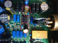
Took some images this morning in better light.
Could someone have a look and see if they can see where i can take a ground from
Thanks in advance
I said before to install them ON THE BACK of PCB!
You could put them right across the yellow electrolytic capacitors right next to the OpAmp. Those for sure have one pin to ground and another on power rails.
But I see, in the last pic, that looks like you already have two ceramics there - is the little blue ones next to the electrolytics, exactly like the ones recomended by me...
If you didn't see that for a week now, I think this "upgrading" task is over your skill level.
Last edited:
I said before to install them ON THE BACK of PCB!
You could put them right across the yellow electrolytic capacitors right next to the OpAmp. Those for sure have one pin to ground and another on power rails.
But I see, in the last pic, that looks like you already have two ceramics there - is the little blue ones next to the electrolytics, exactly like the ones recomended by me...
If you didn't see that for a week now, I think this "upgrading" task is over your skill level.
Yes i know they are to go onto the back. But you asked for pics. No markings at all on the back, thats why i sent you pics of the front of the pcb, to see if you could see a ground near the opamps.....
Yes i know there are ceramics, there are lots of them on the board. But i do not have a schematic, and assumed that since you told me what to do, without seeing what was on the board that you knew exactly what needed done.
I never claimed to be an expert, everyone has to start somewhere!!!
Ill check those ceramics tonight and see if any of them are decoupling the opamps on the v- v+ pins...
Please be patient, I'm still learning, but learning fast 🙂
As i said back at the start..... This is a learning project.
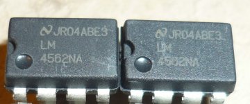
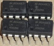
While in glasgow today i popped into RS And got 2 opa2134pa opamps. (the original ones)
After a short listen I am reasonably sure that the muddy bottom end and harshness was due to the opamp change.
Ill have a good listen later on, and maybe do an A B test with the lm and opa opamps. See if i can confirm.
Thank you again sonic for your help and infinite patience.
Suppose the only way i could be 100% sure there are no issues is to buy a scope, but need to learn how to use one first 🙂
Let you know how i get on.
Regards
I can tell you 100% that those capacitors are on the OpAmp supply already.
Yeah i see them now you point them out. Still got a LOT to learn 🙂
Wish i had spotted that before i went to maplin.
Learn something new every day.
I need listen no longer. What a difference!!!
Was definately the opamp change that caused the issues with the bottom end and the hashness at the top.
After installing the opa2134pa opamps it sounds superb again.
Im puzzled why the lm4562's sound so bad, from what i have read, and been told they should have sounded much better??
Can anyone think of a reason for this happening?
Regards
Where did you buy them? Do they look like below? Those are samples straight from National Semiconductors (before they where aquired by TI).
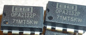
I am showing my OPA2132 that I did compare to.
I am showing my OPA2132 that I did compare to.
Attachments
Last edited:
- Status
- Not open for further replies.
- Home
- Source & Line
- Digital Line Level
- Dacmagic1 after upgrade. Some advice please.