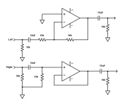
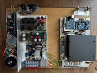
Sorry, I think I underestimated the project. My schematic is simply the one posted on the website. The only addition I made was the potentiometer.
You don't have too much more to do, just a few parts to add.
You have a 10k value stereo volume control at the main outputs?
Yes, exactly, it's the beginning of the B1 by Nelson Pass.You have a 10k value stereo volume control at the main outputs?
Thank you for the help. Today I will start by connecting the recommended power supply board for the DAC and will post the oscilloscope results from the DAC output here.
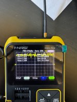
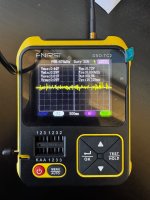
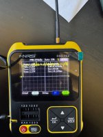
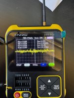
Good morning everyone, I disconnected the part of the circuit I built, connected the recommended power supply, and tested the output directly from the DAC. Here are the results.
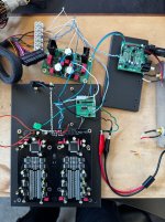
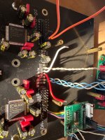
The first two photos show the oscilloscope on the non-inverted Out- channel in AC and DC, and the second two on the other channel, also in AC and DC. The last photo shows how I connected the components.
How should I proceed now?
Thank you again for the help you are giving me.
The first two photos show the oscilloscope on the non-inverted Out- channel in AC and DC, and the second two on the other channel, also in AC and DC. The last photo shows how I connected the components.
How should I proceed now?
Thank you again for the help you are giving me.
Attachments
In the top left corner of the image in post #2, shows two jumpers that need to be placed. Are these connected?
With the positive schematic you posted, could I make it work?Ok, then maybe something like this. The 10k output resistors are the volume controls.
Don't forget the decoupling capacitors on the op amp power supplies.
Sarei interessato anche io al progetto, se ti stanchi delle schede da7 potrei acquistarle per giocarci un po' 😀, ma ti auguro di riuscire. 🤞
ottimo, bellissimo lavoro. Peccato l'uscita con operazionali, poi hai 2 schede esci in bilanciato o converti con trasformatore?! 👍

Avrei voluto evitarla, ma non ne ho le competenze tecniche. Tutti i sistemi per unire segnali opposti che ho trovato facevano uso di operazionali. Alla fine ho usato il filtro di ricostruzione di JLSound che avevo già in casa. Se hai altri metodi per consigliarmi sono tutt’orecchi!
Io ho usato una scheda cinese con trasformatori supermermaloy 600 : 10k per intenderci quelli che monta Ian Canada sul suo I/V passivo.
Nel tuo caso, raccogli il doppio segnale bilanciato e lo sbilanci un trasformatore...
Molto più semplice di come hai fatto tu.
Nel tuo caso, raccogli il doppio segnale bilanciato e lo sbilanci un trasformatore...
Molto più semplice di come hai fatto tu.
È davvero così semplice? Ho visto che li vendono su Audiophonics. Li collego alle uscite del da7 e ottengo il segnale sbilanciato da collegare al pre?
Si, alla fine per quello che costano, ci si diverte e suonano anche bene, probabilmente meglio degli op
- Home
- Design & Build
- Electronic Design
- DAC R2R Construction