rfbrw said:
Which, unless I am very much mistaken, shares a loooong land border with Norway. Trolls do not recognise borders.
Hehe 2 - zero to you.
😀
rfbrw said:
Thanks but no thanks. I am no fan of the ASRC but the analogue stage is always of interest.
Schematics for the analog stage is found here
schematics
The PSU´s are found on page 7 in this thread.
But the analog stage is actually engineered and intended for use with this DAC Chip, and nothing else. You might though be able to change the gain and filterring, to use it with an I out chip such as BB or AD. Btw it has to be protected against HF output from the chip, as it just passes it on further down your chain, which could be disasterous.
Be aware of the missing servo circuits. If not used with a chip that has some DC output, you might even be able to avoid the servos, and adjust DC manually, because the analog stage is very stable on that matter, only temperature drifting and inaccuracies in the components is cancelled out by the servos in our implementaion. This means a cut of frequenzy in the milliHz region. If ypu have servos further down the chain, they might be able to cancel out minor values of DC ofset.
The transistors used are ROHM GP types.
All film caps are Wima PP or similar, electrolytics are Panasonic FM.
Pay atention to the PSU´s for the analog stage. It really needs a very low impedance and low noise supply, as the general PSRR in this stage cannot compede with the values op-amps can present.
The ASRC will always be a matter of discussion, as it completely recalculates the incomming data. But IMHO you cannot at all compare the upsampling of 4192/1896 with the oversampling in digital filters. The upsampler is very superior in this comparison, if fed by a deacent clock and supply.
Havoc08 said:
Nothing judging by the pictures...
Hurtig and KvK did the exact same thing on a Danish audio forum... I think it's just their way to spend time, don't let the troll catch you 😉
I'll unsubscribe this lousy thread from now.
True... Some 2 years ago, we were accused of marketing on a danish forum. They told us that they were sure that we were trying to sell our products on their forum.
But now 2 years after, we still have not sold any (Except 1 prototype that I aggred to sell to another user).
I wonder if we will also be officially accused of selling the DAC here

If that is the case, I guess I won't spend more time making schematics and PCB ready for all you guys... 😉
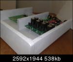
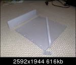
A few shots of the enclosure taylormade for the DAC and PSU PCB´s
The enclosure is made of aluminium, top and bottum is 5 mm, front and sides, as well as the separation in the midle, is made of 10 mm aluminium. Top and buttom is held in place by 10 pcs. of 4*10 mm screws each, which makes the enclosure rock solid and free of vibrations that might cause sound colorations, but without looking bulky.
The finish is pretty rough yet, because it has only been treated with glass and soap so far. But it surely looks both dazling and compact to me anyway.
Attachments
Last edited:
At the time being, the DAC is now on its way to its final trim.
The latest changes has been in the timing device for 1896. Both an oscillator and a discrete clock is to be tested. By now it features an integrated oscillator, which has pretty impressing data, but as always it is impossible to obtain jitter data below 12 KHz. The discrete clock does hve nice data from 20Hz and up, but it can hardly compede with the oscillator above 12 KHz. So it is not a win win situation to choose either of them, and I belive that choosing both will cause more trouble😀. Maybe this could become some kind of patent to combine two or more clocks with different strengths
During the development proces there were no need for a clock, as the PLL in the reciever did a fine job, but after the 1896 asrc came in to the project, a seperate clock was needed. At first LClock XO2 served as external clock, and now a 25MHz oscillator, which I find much better than the XO2 solution, and that is some kind of puzle to me. The XO2 is a very low jitte discrete clock with separate PSU. The only theoretical drawback that comes with it, is the need for leads, which of course were held very short, but still the cheap integrated oscillator with unknown low frequency jitter performs a lot more smooth and natural.
And this has actually happened every time I´ve tried to use a seperate clock device. I know that a lot of DIYérs swear to seperate, precise clock devices, but I simply like them most, when they are taken away. Prior to this I´ve heard them in my Denon S1, and in some different Sony CD´s and SACD´s, and of course in LC Audio´s own CD player. Every time it was a very clear "no go". This time, and also in my memories, the sound suffers from emphasized focus on expansion. Your atention is drawn towards the dynamic headlines in the music, which at first glanse seems impressing and entertaining, but at the end of the day, it comes clear, that this is not really musical content. The cheap oscillator is quite contrary to the discrete clock, your atention isn´t really drawn anywhere special, and the flow and timbre becomes very natural, and detail is both musically integrated and easily understandable, in fact it reminds me of class A amps. So my guess is that we will end up with a state of the art oscillator, although the discrete clock will also have its chance in due time.
But still this is a puzle to me, why is it that very precise discrete clocks mostly is a "turn of" like that?
Theoretically the best clock would be the one with the most clean and vertical edges, lowest jitter and with the output voltage @ precise the voltage where the timed device performes at its best - 3,3V for AD1896.
All these parameters are higly regarded in i.e. LClock XO´s and I really don´t think, that anyone honestly can achieve better jitter data than these devices.
@ now it seems to me like either the jitter game is completely different, or that the leads needed when using an external clock ruins the low jitter achievements, even when using high frequency capable leads as i.e. RG 174.
I guess we will end up using a integrated XTAL-Oscillator, and not the integrated.
Currently we run on a standard integrated version.
As KvK wrote, we did test a LC Audio LCLOCK XO2, that would perform significantly better than the standard XTAL oscillator. But in listenings-test, it really did not.
Therefor it may not be worth the effort, to implement a "High Performance" clock, since a integrated version performs better. We still must try different versions of the integrated to find the best one. This will be done in the very near future.
No schematics...
This is a product plug. This pathetic thread should be closed.
Agreed, waste of time discussing this project further.
@MWP!
Well you can feel free to feel what ever you want regarding our project.
To us no ones feelings are of any use at all, in developing equipment like this.
If you feel set aside because we do not want to share this project with people, who cannot do it with the info and hardware already provided, then so be it, because it would probably not be succesfull anyway.
Actually we have been striving to keep emotions as far away from the development proces as possible.
The facts are at the time being as follows:
A few PCB´s for both PSU and mainboard exists and can be bought from us, at a very very reasonable price.
A partslist can also be mailed to you, I think most parts is in stock at Digikey.
Schematics only exists as they were published in this thread already, and no further work will be spend on that.
You can have close up fotos of both sides of the PCB.
Regarding the timing device, a little while will pass on before the final design and PCB´s are ready. Until then you can use an oscillator with a few decoupling caps.
From there on you are on your own.
It might turn out to be pretty hard to assemble the PCB, as it is very compact, and hardly contains anything than the smallest SMD components ie. Micromelf resistors.
But if you get your DAC running, and if it is not tampered with or changed in anyway at all, you will be able to amaze anyone with its completely unrestrained and elegant performance. Actually circuitry like this is mostly found in gear costing a lot more than 10K$, so go for it, or wait for the simpler project.
This project btw. has been intended to provide ourselves with a state of the art DAC, with performance beyound any commercial DAC, but as the project went along, we realized that we could not do only two or three pieces. As a result of that, we decided to make as few more as possible, these we will share with those interested, but we also realized, that this is not a kitchen desk project at all. It calls for soldering skills and understanding of electronic circuits, so that you actually already would have sufficient information to get on with the project on your own.
So if you think you lack info regarding this project to build it yourself, we strongly recommend you to wait for the more simple project comming soon.
Anyhow there is still a few PCB´s available @ a redicoulus price, so feel free to give it a try.
Anyway the last edition of the scematics will follow ASAP.
Last edited:
@ MWP:
I really do not understand, why people are so busy, claiming that this is a commercial project, that we are try sell.
I know it may be very hard to some people to understand, but it really isn't intented as a commercial project. But I will once again try to explain what is going on, for those who seem to have a very hard time understandig:
------------------------------------------------
Despite the name of this thread, the project is not yet finished, since we discovered some possible upgrades that needed to be tested.
This is NOT intended to be just some other DAC like many DIY-projects.
The idea has always been to develop the absolute best DAC ever seen. And already now we feel quite sure, that we have reached our goal.
But since we stille have a few small changes that we would like to test, we have not provided any schematics. Simply because we feel, that it will go against our philosophy to provide something "almost done". Again... There are to many of these "almost done" design floating around, both as DIY and commercial products.
The idea has always been, to provide the schematics as soon as the project is done. I really do not understand, why people want some "almost done" schematics. Maybe MWP can explain to me.
------------------------------------------------
But.... We have decided to upload the scehamtics as they are. I must emphasis, that these are NOT final.
The schematics represents the DAC as it is right now, and will perform extremely well. We do believe, that there is no better DAC out there, but can not guarantee, that there will not be any upgrade, since the design is not locked yet.
To achieve maximum performance, some guidlines must be followed:
- The PCB is very important. Bad layout = bad sound!
- Use only the components specified. Different value or type/brand/series, will result in different sound. This is very important, since all component types is optimized by listening tests.
- To build the DAC calls for some serious soldering skills. I would be happy to see a lot of people enjoying the DAC. But since this is a DIY project, you are on your own making it work! Following the schematics and good PCB layout, the design is absolutely stable!
- Be aware that some components needs cooling (Voltage regulators)!
I will upload the schematic within an hour or so....
I hope this will stop the constant accusations of us trying to sell our product.
why not use a da chip without builtin capacitor ?
Somehow i dont like the idea of metal oxide capacitor in series... You have an ASRC, you can easily produce 20bit rounding for r2r...
Somehow i dont like the idea of metal oxide capacitor in series... You have an ASRC, you can easily produce 20bit rounding for r2r...
Schematics
As promised, we will provide the schematics.
Again I must emphasis, that these schematics is NOT locked yet. We still do some R&D on them, to go even further.
The schematics provided will result in what we believe to be the best DAC ever seen. But performance depends very much on implementation.
The BOM is not finished yet. But we use ROHM GP transistors for the analog stage. For the shunt regulators, we have not yet decided.
All electrolytic capacitors is Panasonic FM series. non-polar capacitors is Wima film types.
The schematics do not show transformers. For the digital stages, connected to J501 and J502, use 2x12VAC. For analog stage J503 an J504 use 2x18VAC.
We use 10VA UI transformers.
The clock module is not yet finished. Use a 25MHz/3,3 volt master clock.
Hope to hear from some of you guess who has asked for the schematics, when you start building the DAC.....
Since the schematics is NOT finished yet, I can not guarantee that there is no errors. If you find any, please let me know.
Attachments
why not use a da chip without builtin capacitor ?
Somehow i dont like the idea of metal oxide capacitor in series... You have an ASRC, you can easily produce 20bit rounding for r2r...
I'm not sure I understand. What kind of D/A chip do you have in mind?? We do not use any capacitors in series with the signal.
Also... I know that as soon as the schematics is public (which is the case now), people will start arguing about some changes.
Please understand, that we have used approx 4½ years tweaking on this design (The prototype ran about 4 years ago). Any part of the design have been tested with various parts.
We believe that this design has been through more R&D, than most commercial "High End" DAC's.
Feel free to make changes to the design, but be aware that performance most likely will degrade.
okay Im the first to download : )) Thanks for the effort. Both the Cirrus and AKM dac have capacitors inside, in fact anything but old r2r does.
okay Im the first to download : )) Thanks for the effort. Both the Cirrus and AKM dac have capacitors inside, in fact anything but old r2r does.
I think that you are thinking about the switched capacitor filter in these two chips.
you cannot consider these as capacitors in the signal path. A switced capacitor can be set up as both a Digital to Analog converter, as an inverter and as i.e an anti aliasing filter, which is precisely what it does in the CS4398.
But it has nothing to do with "normal filtering" with both inductors and capacitors.
I think you might read a bit about SCF here http://en.wikipedia.org/wiki/Switched_capacitor .
And the chip chosen was actually chosen because of sonic reasons.
We think this is THE chip, as long as it does not have to be an I out chip. The I out chips in our minds were discarded, because we could not equal the sonic performance of 4398, regardless of I/V stage design. Maybe some day, but by now it seems quite difficult, to get the theoretically superior performance of BB DAC Chips to materialize. Btw. in spite of our very positive attitude towards TI chips, we could not obtain performance any better than from the U out types tested. Maybe the upsides of BB´s superior data is ruined by the neccesary I/V stage.
Last edited:
okay Im the first to download : )) Thanks for the effort. Both the Cirrus and AKM dac have capacitors inside, in fact anything but old r2r does.
OK, now I see....
Well... A little history:
- Kurt von Kubik used to be a hardcore Burr Brown Multibit fan.
- I had worked with D/A chips from Crystal (Cirrus Logic) during my engineering studies, and has always believed them to be state of art. On the other hand, I knew of the advantages of an R2R D/A chip.
Based on that, we did start the project using PCM1702K and PCM1704K. But somehow, these chips did not really impress us that much.
Therefor I suggested the CS4398. And believe me... That caused quite a few discussions (KvK will most likely agree to that 🙂 ). But KvK accepted to give the CS4398 a single chance. And the result was really impressing!
Since then, we have tested every possible DAC chip on the marked, that seems just a little interesting. But nothing compares to the CS4398!
We have seen some tests claiming that the CS4398 isn't that good. My guess is, that this is caused by non-optimized implementation.
Bottom line is, that we have not meet any other D/A-converter, that will follow this one even in the price range above $25.000, nothing has impressed us like this DAC. Anybody curious to find out how good it performs, are more than welcome to make an appointment, to audition the DAC before starting to build it.
We are planning to build one extra DAC, that will be available for test. And yes, we do this even though this is now an open source project! Simply because we hope to give as many people the great experience of this design.
Also... User on Danish HiFi forums will know, that I have claimed the High End HiFi industry to be way out off line when calculating prices. This design will show, that true High End does not need to cost $10k+. This design really proves this to be true.
Last edited:
As promised, we will provide the schematics.
Fair is fair; thanks.
JeroenR
Well!
I´ll have to admit, that I was at first prone to choose the top BB type of DAC, as our project started. But at the very beginning my favorite chip went NRND, this was actually the reason for further research. I admit that I was not completely unbiased in this matter.
But before anyone turns his or her attention towards the digital part of the design alone, I´ll have to put this a bit into perspective.
Both Accuphase, Weiss, Meitner, ML and others have their favorite chips, principals and even propritary digital designs, but every single one of them, ends up putting the whole thing throug a bunch of cheap op-amps sounding precisely as op-amps do. Even analog PSU´s are left completely standard. We´ve tried this out many times, and it just sounds completely wrong in their own different ways.
In our design PSU´s have been designed as though the amplifiers and digital circuits did hardly have any PSRR at all. In other words, the problem was solved at the source, so we did not have to do a lot of circuitry to gain PSRR in the amps or so.
This makes it reasonably simple, solid, stable, and most of all, healthy and strong from the very beginning, leading to NFB design and a capacitor free signalpath. All of this is only common in top notch models from i.e. Esoteric, Krell, Denon and very few other makes @ top $ prices.
Now be fast, and do one yourself. I can hardly wait to hear your opinion.
Fair is fair; thanks.
JeroenR
No problem 🙂
It's just frustrating to spend so much time on a project (4½ years), and then being accused of product hiding a commercial product behind this DIY project.
I would have liked to wait until the design is 100% locked, to provide the schematics.
Will you consider building the DAC??
Now be fast, and do one yourself. I can hardly wait to hear your opinion.
we just finished outlining the volume attenuator design (after 2 years
 ), which grew to be a very interesting one and Im goin to utilise it on the same PCB . I am too interested, what do you think of buffer IC-s like buf634 and LME49600 ? Are those considered 'opamp sound' contributors as well ?
I have not listened to LME49600. But I know BUF634. If you ask me, it sounds just like any other "op-amp"!
Funny.... People spend so much time swithing op-amps and telling how much better it sounds. In reality, theyall sound so much the same, which may be the reason that people keep switching them.
Try a good discrete analog stage, and you will never waste time switching op-amps again.
If you really must use an op-amp, go for the old fashion NE5534! It's not the best specified op-amp, but real life listening test often points towards NE5534.
- Status
- Not open for further replies.
- Home
- Source & Line
- Digital Line Level
- DAC project completed