I remember reading a post by @abraxalito where he recommended a passive analog filter, especially for multibit dacs. I'm playing with an NOS multibit dac and thought I would try no filter and passive filters of a few slopes to see what the subjective sound differences are.
As I started simulating the filter, I realized how critical the input impedance and output impedance of the filter can be in the output response of the filter.
My first question is if I am correctly representing the impedance in my model? I'm using Micro-Cap 12 for simulation. In the schematic, I am using a pure AC voltage source with a resistor in series representing the output impedance of the dac. I am also using a resistor as the load representing the input impedance of the pre-amp following the filter. The load resistance is much less sensitive because it is a high impedance compared to the filter.
The listed output impedance of the dac is 625 Ohms which should be OK feeding a pre-amp but seems to have a large affect of a passive filter. Happily this can be tuned out of the system but I'm curious if others have found this in practice?
As I started simulating the filter, I realized how critical the input impedance and output impedance of the filter can be in the output response of the filter.
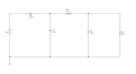
My first question is if I am correctly representing the impedance in my model? I'm using Micro-Cap 12 for simulation. In the schematic, I am using a pure AC voltage source with a resistor in series representing the output impedance of the dac. I am also using a resistor as the load representing the input impedance of the pre-amp following the filter. The load resistance is much less sensitive because it is a high impedance compared to the filter.
The listed output impedance of the dac is 625 Ohms which should be OK feeding a pre-amp but seems to have a large affect of a passive filter. Happily this can be tuned out of the system but I'm curious if others have found this in practice?
Attachments
You don't say what the particular DAC chip is so I'm unclear whether your simulation of the DAC as a voltage source with a series R is the best way to go about it. Your DAC chip could be a voltage out or current out type - my hunch is its a current out type with a 625ohm output impedance as that number sounds a bit high for a voltage out DAC. If its a voltage out DAC then I'd plug that number (its max output voltage) into the voltage source to give its max output amplitude. If its a current out DAC then change the voltage source to a current source in the schematic and move the 625ohm resistor to be in parallel with the current source. The (voltage source + series R) and (current source + shunt R) combinations are equivalent networks in the theory, called Thevenin and Norton.
https://www.allaboutcircuits.com/textbook/direct-current/chpt-10/thevenin-norton-equivalencies/
If your DAC truly is a current out one then one thing that's worthy of attention is the output compliance. Many Iout DACs have a very restricted output compliance range (under 100mV typically) - this restricts the maximum output level that can be had when using a purely passive filter.
Thank you for replying. The DAC is a discrete R2R ladder (The Well Audio DAC-lite) and it's a voltage output with a maximum output voltage of 1.8V. I was also a little surprised that it had such a high output impedance but it seems to be manageable. And thanks for the reference to the Thevenin-Norton equivalence. I seemed to get confused by those concepts. Thanks for your help.