I read that with 12v or more, the AD811 gets very hot and needs a heatsink.
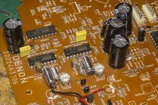
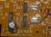
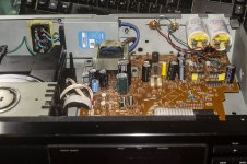
The application for the I-V converter is to upgrade a Denon DCD-590 I got for nothing. It's using dual PCM61s but instead of having an analogue output stage with opamps like most of the dual PCM61 CDPs I've seen, it uses the Vout of the DAC chips and a 10uF DC blocking cap. The digital filter is the SM5840.

The application for the I-V converter is to upgrade a Denon DCD-590 I got for nothing. It's using dual PCM61s but instead of having an analogue output stage with opamps like most of the dual PCM61 CDPs I've seen, it uses the Vout of the DAC chips and a 10uF DC blocking cap. The digital filter is the SM5840.
Attachments
Hi folks
I want to build an output stage for current output DACs such as the PCM61 so I have been looking at I-V conversion methods.
Rather than use the op-amp built into the PCM61 it is better to use an external opamp with better specs. The op-amp inside the PCM61 DAC chip has a slew rate of only 12V/uSec but to properly reproduce the signal coming out of the DAC the opamp should have a slew rate of 1000V/uSec.
The AD811 has been widely used for I-V conversion and has a slew rate of 2500V/uSec. I don't have any of those and they are expensive, but I do have several AD812s, which is the dual version and has a slew rate of 1600V/uSec.
The PCM61 also requires the external opamp to have close to zero input impedance, which the AD811 offers.
Anyways, after research I found lots of people had successfully used the AD811 with the PCM61 or one of the similar Burr-Brown DACs.
I don't see any reason why I can't substitute the AD812, but I haven't been able to find any circuit schematics specifically for the AD811/2 as an I-V converter.
So does anyone have a suitable schematic for an I-V converter using the AD811/2, or can I just use something like the scheme present by Herbert Rutgers:
https://www.by-rutgers.nl/IV-converter.html
I used 4X AD811 with dual differential 1704's.
1704 has a minuscule current out of +/- 2mA and the only way I could get 1704 to sound decent was with AD811.
You can not use the Cf with AD811 - the IC will oscillate if you do.
Do not use more than 10V + and - for Vcc / Vee. Place the heatsink on top of AD811 (DIL package).
The circuit I used as a template starting point was Walt Jung "High Performance Audio Stages Using Transimpedance Amplifiers". The dynamic impedance loading as seen by 1704 was apparently close to 0 ohms - ideal loading.
The following differential to single-ended IC (and an analog filter) was LM6172.
I also tried AD812 - but was very disappointed with the result. AD812 is definitely not 2 X AD811; the key spec to look at, in this instance (of 1704 in particular with such a low current-out value, or any current-out DAC requiring close to 0 impedance loading) is the - Input Resistance; AD812 is almost 5 times worse!
Good luck.
There's a worrying amount of current noise from it too for the same reason, but I guess the impedances of the feedback network are low enough to tame that, but its worth checking.Please consider the 14 ohm neg. input resistance
With CFB amps the designer doesn't have complete freedom of choice over the impedance of the FB network as below a certain value the amp goes unstable. So its not possible in practice to mitigate that -ve input terminal current noise by setting the FB network impedance arbitrarily low.
TDA1547 is a bitstream DAC chip, no need for I/V there. But it needs a modulator (SAA7350 or TDA1307 if I remember correctly).
Yes, but the current output can be drawn from pins 22 23 and 10 11, the current is 0.1mA. For now, I will use the ADA4610 for I / V.
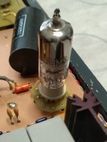
In my stock I have two pieces of TDA1547 and three SAA7550, and soon I will have SM5842 for the filter, I already have PMD100 but it is in the DAC with PCM1702 where I used AD811 before, now I use 6HM5 tubes for I / V.
Attachments
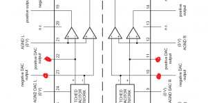
How do you stop the on-chip opamps of the TDA1547 interfering with the S-C DAC output current when you connect an external I/V opamp?
usning the AD844 as an IV
I did use the AD811 for a long time, but now I did build the IV converter with the AD844. Much better because the lack of feedback, espacially the bass. See: 'Using the AD844 as an I/V' on DIYaudio. I have a TDA1540 dac with Grundig DEM mod and 5 parallel AD844.
I did use the AD811 for a long time, but now I did build the IV converter with the AD844. Much better because the lack of feedback, espacially the bass. See: 'Using the AD844 as an I/V' on DIYaudio. I have a TDA1540 dac with Grundig DEM mod and 5 parallel AD844.
for replace AD844 go to the information to post #5 under
Choosing of best sounding OP AMPs for the lowest possible THD+N -really the best Way?
and
Using the AD844 as an I/V
Choosing of best sounding OP AMPs for the lowest possible THD+N -really the best Way?
and
Using the AD844 as an I/V
How do you stop the on-chip opamps of the TDA1547 interfering with the S-C DAC output current when you connect an external I/V opamp?
Configure the op-amps as buffers. Connect the negative input to the output.
On the schematic, the S-C DAC's output goes direct to the -ve input. So if you connect the -ve inputs to the outputs, how to extract any current? The 100% negative feedback will give a very low impedance load to the S-C DAC.
It is what Philips do with the opamps on the SAA7350 when it is paired with the TDA1547 but looking closer there are significant differences between the two. That idea won't fly very far, if at all.
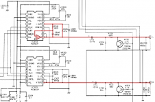
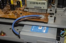
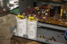
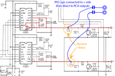
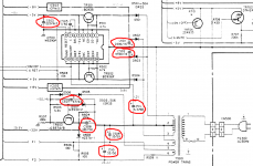
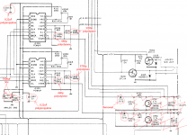
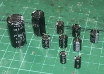
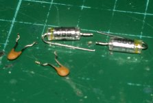
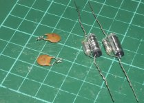
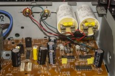
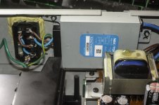
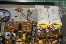
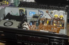
Well, the application I had in mind for the I-V converter was to upgrade this Denon DCD-590, but having reworked the player a bit by replacing the caps in the LPF with polystyrene ones (Denon, the cheap bastards used ceramic disk ones!) and then bypassing the rest of the output stage to a pair of 6uF polypropylene caps, it sounds pretty good actually. I also added an NEC/Tokin noise filter to clean up the AC input and replaced all the large electrolytics and all the electrolytics in the PSU section.
It actually sounds pretty good in this state, without replacing the dirt cheap oscillator with a proper clock and without giving the DAC chips their own, clean regulated supply, so I don't think I'll bother doing anythign else to this player and just leave it as it is now.
I'll revisit the I-V converter in the future for another project.
Attachments
-
 DSC00571.jpg227.9 KB · Views: 157
 -
 DSC00570.jpg213.6 KB · Views: 192
 -
 DCD-590 Analogue Stage bypass.png123.3 KB · Views: 213
 -
 DCD-590 Power Caps.png297 KB · Views: 224
 -
 DCD-590 LPF upgrade.png312.7 KB · Views: 252
 -
 DSC00566.jpg265.6 KB · Views: 201
 -
 DSC00564.jpg365.8 KB · Views: 183
 -
 DSC00562.jpg371.2 KB · Views: 237
 -
 DSC00561.jpg203.6 KB · Views: 192
 -
 DSC00560.jpg241.9 KB · Views: 180
- Home
- Source & Line
- Digital Line Level
- DAC Output Stage using AD812