Hello, Sergio!
It's good to see that you are still making innovations on your interesting transimpedance open-loop Tagus-X circuit. If you have any simulated distortion plots for this version, could you post? Thanks.
By the way, I also find the occasional linestage (high input impedance) transconductance variations of the Tagus-X just as interesting.
Sergio,
Welcome back
thank you for sharing your Ideas
Is there a chance to remove coupling cap using dc servo and 6.2 mA ccs Injected to the Input
Welcome back
thank you for sharing your Ideas
Is there a chance to remove coupling cap using dc servo and 6.2 mA ccs Injected to the Input
Sergio,
Welcome back
thank you for sharing your Ideas
Is there a chance to remove coupling cap using dc servo and 6.2 mA ccs Injected to the Input
1) Q7 sinks the PCM1794A's 6.2mA output bias current.
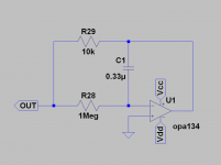
2) An inverting op-amp servo could be attached right at the circuit output. Where the servo's input and it's output both are connected to the same point, which is the Tagus-X output node.
Ken Newton,
thank you for explanation
Is this strategy, feeding output to Input a preferable compared to ccs of 6.2 mA connected at Input
Is there a way to use schematic with both + and - dac outputs - when they get summed offset got to go to 0 and there Is no need for Injection of 6.2 mA, but also dynamic range Is bettered
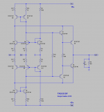
Tagus DIF
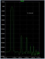
Here is what you are looking for Alexander, The distortion is 0.00004% at 1v rms and 0.00016 at 2v rms.
Is there a way to use schematic with both + and - dac outputs - when they get summed offset got to go to 0 and there Is no need for Injection of 6.2 mA, but also dynamic range Is bettered
Here is what you are looking for Alexander, The distortion is 0.00004% at 1v rms and 0.00016 at 2v rms.
Attachments
Hello, Sergio!
It's good to see that you are still making innovations on your interesting transimpedance open-loop Tagus-X circuit. If you have any simulated distortion plots for this version, could you post? Thanks.
By the way, I also find the occasional linestage (high input impedance) transconductance variations of the Tagus-X just as interesting.
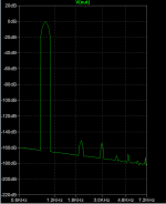
Hello Ken, thank you for your kind words, distortion at 1v
Attachments
Sergio,
appreciated very much
I can say that this Is absolute best for pcm1794 but also other diy friendly chips like pcm63, pcm1794 when you set them two per channel
just one more question - how can we fine tune to 0 output offset
regards
appreciated very much
I can say that this Is absolute best for pcm1794 but also other diy friendly chips like pcm63, pcm1794 when you set them two per channel
just one more question - how can we fine tune to 0 output offset
regards
Last edited:
Hello Ken, thank you for your kind words, distortion at 1v
Wow, the highest harmonics are 150dB down! Essentially, distortion free operation is predicted. One of the Tagus's implementation aspects which I always found very interesting is that it doesn't much depend on the matching of transistors. While some versions do appear to utilize a short local feedback-loop around each folded-cascode, there's no global feedback. Impressive.
I note that the single-ended circuit appears to features 20dB lower distortion than does the differential version. Is that mostly to do with the differential version canceling the PCM1794A bias current as D.C. common-mode, but, in doing so, that causes the Tagus-X circuit bias to be imbalanced?
Last edited:
Sergio,
appreciated very much
I can say that this Is absolute best for pcm1794 but also other diy friendly chips like pcm63, pcm1794 when you set them two per channel
just one more question - how can we fine tune to 0 output offset
regards
To have ov at output and very low distortion we must have the best current mirrors we can, so resistor (r18,r19,r20,r21) should be 100 ohms and must be at least 0.1%, best is 0.01% tolerance, the bjt Q7,Q8 and Q9,Q10 ideally should be dual transistors like the BCM847DS and BCM857DS this transistors are SOT457 witch is easy to solder, they have Current gain matching and Base-emitter voltage matching with max 2mv difference.
with a 0.01% error in the resistor we get 1mv in output and 0.000023% distortion, with 0.1% error 7mv and 0.000055%, with 1%error we get 80mv and 0.0006%
APC1206T100RZ ARCOL / Ohmite | Mouser Portugal
https://pt.mouser.com/datasheet/2/916/BCM847BV_BS_DS-1517738.pdf
I note that the single-ended circuit appears to features 20dB lower distortion than does the differential version. Is that mostly to do with the differential version canceling the PCM1794A bias current as D.C. common-mode, but, in doing so, that causes the Tagus-X circuit bias to be imbalanced?
the Pcm1794A bias current is not a problem at all, the differential version use a current mirror that have some limitations, the Tagus X circuit are feed with current sources with very high impedance so the current variations at the input of the circuit don´t have anywhere to go but to the output of the I/V converter I also make sure that there is no early effect distortion,
Attachments

Hi Serjio,
regarding differential version
using dual matched transistors for current mirror Is great Idea
I guess that also It Is recomended to have all NPN and PNP pairs closed or even better, matched
as we know there Is no Ideal things In real world, can we do fine tuning of output dc offset If we use potentioneters at R18, R20
still not sure about dc offset trimming of final Q1, Q2, Q3, Q4
what Is output Impedance and do we need to add buffer
regards
Last edited:
I think a DC servo would be a good option, so no manual trimming of DC offset would be required.
I am will to do a pcb layout of this design but it should be a complete DAC with SPDIF interface. Makes it self contained and easier to test out.
I have most of this done, never built it, it was some time ago so it would need to be gone over again.
I am will to do a pcb layout of this design but it should be a complete DAC with SPDIF interface. Makes it self contained and easier to test out.
I have most of this done, never built it, it was some time ago so it would need to be gone over again.
what Is output Impedance and do we need to add buffer
The output impedance is 360 ohms for 2v rms output and 180 ohms for 1v rms , no need for buffer.
orcad
It is a back burner for me but I would like to design a good DAC with digital interfaces some day.
I did up a CS8416 design a while back, using the PCM1794A with the application ckt, but never got it done. The clocking needs to be re-worked, I should I think be using RMCLK o/p, as I recall it was not done right. I have a few examples from other designers.
See what you think.
Attachments
Last edited:
Sergio,
thank you for reply
DC servo Input and output (out from post 854) are connected at the output of IV converter - both tagus X and tagus diff, Is that correct?
If you looking for 4 spdif Input, AK4118 digital selector / receiver Is proper choice
thank you for reply
DC servo Input and output (out from post 854) are connected at the output of IV converter - both tagus X and tagus diff, Is that correct?
If you looking for 4 spdif Input, AK4118 digital selector / receiver Is proper choice
Last edited:
why? experience? it does look like it is a good part to use, 0.5mm pitch soldering can be an issue for some.If you looking for 4 spdif Input, AK4118 digital selector / receiver Is proper choice
What are the types of distortions that really need to be lower and by how much lower with an i/v stage so that any i-out dac ever made would give you the best listening impression?
I've seen that the circuits depicted here have tons of components and ignoring their number and the surface occupied by the circuit itself as well as the thermal compensation which has no chance to be good enough is a big problem when aiming to such lower numbers.Basically i really doubt that you can control those distortions in real life to such a degree, but i also KNOW that there's no need to have such low HARMONIC distortions because they are harmonic...a term that comes along with "harmonious"...Actually i don't even care of any circuit performance once it claims to be better than -90db THD+N...Even more, there's no way on Earth that you can be aware of any -90db THD.Unless you're listening in a completely isolated room you won't even be able to hear anything wrong over -80db...
There are lots of people listening to simple 16 bit CD's on good CD players (like me)telling that they hear weird noises due to the I?V stage, DAC or any other cause while nobody's questioning the dithering process which is done by the sound engineer during the mastering or automatically by the DAC or other DSP's...and many of them are simply wrong.When you get to superior sampling rates and bits the cheapest op-amp can do the i/v with very good results , but then , nobody's questioning the recording process , how good are the engineers at mastering a musical material on high quality recording equipment. There are so many bad recordings on the market that's really a shame to put a blame on the audio equipment. It happened for me to listen a Tori Amos CD(16 bit) on a very good player and i simply thought that some songs had smth wrong because of my players, until i bought the remastered vinyl and i have a really high end setup on vinyl.You wouldn't believe, but actually the same parts that were screwed on the CD were screwed on vinyl too, so i had one analogue and one digital copy of the same album that had the same problems.That was the album from the 90's so i blamed on the old digital recording technology until i stated to buy good cd's from 1985, 86, 87 made by RCA, CBS and others and some of them have a wonderful sound, really , really good sound on any player...so I figured that the problem is in the recording process , not the equipment.
For that reason i believe that actually we need a HIGH THD version of an I/V for BAD recordings 🙂
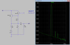
simple I/V
Nothing is simpler than doing an i / v converter for pcm1794 with very low distortion. 🙄
This is an I / V that I built some time ago, as psrr is zero the power supply has to be noise and distortion free.
Perhaps a good idea is to use a 9v NIMH battery with a large capacitor in parallel, this circuit only consumes 6.2mA and the distortion is ultra low if you have the ability to make a good power supply. 😉
Attachments
- Home
- Source & Line
- Digital Source
- dac I/V convertion with very low distortion