Quick question (for sound point of view, not safety please): correct to put the DAC chassis at ground in a single point, or better leave it floating?
Better via a resistor in parallel to a cap (like 10 ohm || 47 nF) o just a straight wire?
Better via a resistor in parallel to a cap (like 10 ohm || 47 nF) o just a straight wire?
As usual, it depends on the circumstances. Is the chassis connected to safety earth or are you making a double-insulated circuit with no safety earth? How about input and output connectors, are those balanced or unbalanced?
Based on your ealier posts, I guess everything is unbalanced, but the inputs are transformer-coupled with no connection between their ground and the circuit ground. Is that correct?
For a circuit with balanced connections in a metal enclosure, AES standard AES-48 prescribes that all the shields of all connectors and safety earth (if any) should be connected straight to the metal enclosure and that the metal enclosure should be connected to the PCB at one and only one point. The idea behind it is that the shields of the cables and the metal enclosures of AES-48-compliant equipment will form one big Faraday's cage to protect the circuitry against external RF fields. Ground loops will be practically inevitable, but their currents will only flow through shields and metal boxes and not through the PCBs, and since the connections between the different pieces of equipment are balanced, they are not very sensitive to voltage drop across the shields of the wires.
For unbalanced connections, on one hand, you want to avoid ground loops because of hum issues, on the other hand, you also want to ground everything straight to the metal boxes for RF shielding. It gets quite complicated if you also have safety earth.
Thanks Marcel.
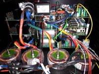
All inputs/outputs are isolated and I use a double isolated circuit with no earth third wire.
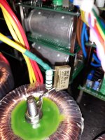
Ok, I don't see any SNR improvements, nor THD%, nor Jitter change, thus I made half way solution, a "ground breaking" single point chassis connection with cap in parallel to 10 ohm resistor. Wire goes to the ground of PLL. It sounds good.
All inputs/outputs are isolated and I use a double isolated circuit with no earth third wire.
Ok, I don't see any SNR improvements, nor THD%, nor Jitter change, thus I made half way solution, a "ground breaking" single point chassis connection with cap in parallel to 10 ohm resistor. Wire goes to the ground of PLL. It sounds good.
Attachments
- Status
- Not open for further replies.