I, like many of you, would like to build my own DACs because I like to build and explore, and also because I am tired of trying to fix the stuff I have and keep up with new USB protocols - I'd like to have the ability to do my own hardware updates.
If I understand correctly, DAC's are generally set up like this:
Digital input interface -> DAC conversion stage -> Analog pre/voltage stage
(And of course a well designed power supply for the whole rig)
Is this correct?
Are there resources out there for me to purchase USB interfaces but build my own I/v, analog, and PSU's? The only resource I'm aware of are the Audio Note kits but there must be more, right?
[Edited and changed I/V to DAC as per iggy's comment below]
Last edited:
There is sort of dac chips, some output with a voltage so don't need I/V conversion only the current output dac chips need.
Yes there are ressource everywhere in the Digital line section to build fron scratch your DAC device, as to buy an USB to dac interface related to the digital front end needed by the DAC (diferent ptotocols you often notice : Spidf, I2S, and so on)
About USB interface it's all about you want to do after and how you connect it.
Good often USB board to DAC advised are JLSOUNDS and Wave I/O boards. There are at Ali as well, but quality may be ??? (you have to know where and whay you buy)
Last edited by a moderator:
So, I need to dig through some threads, read about protocols, and check out boards from the manufacturers you mentioned.
I'm doing some digging through DAC build megathreads, but it's a little overwhelming. I'll keep going.
DIYiggy, are you able to link me to a thread to a DAC that you've built just so I can see an example?
Is I/V typically related to R2R dacs? they're shooting different current through a ladder of resistors and that needs converted to voltage?
If I understand correctly, DAC's are generally set up like this:
Digital input interface -> DAC conversion stage -> Analog pre/voltage stage
(And of course a well designed power supply for the whole rig)
Is this correct?
Sort of. If one were learning about dac system design the first little part of the first lecture might include a simplified model something along those lines.
IMHO sometimes people seem to over-modularize their thinking about audio design. Some other designers may view the power supply as about one-half of the design work. Other designers don't. IMHO it comes down to what they call in the music business 'having ears.' Those designers more picky about sound quality and less concerned about distortion analyzer measurements are more likely to feel power supplies have a lot of effect on ultimate perceived sound quality; that they are not simply modules with defined-performance terminal-properties (without in the foregoing getting into exactly what the term 'sound quality' means).
Last edited:
Sound quality in reproduced version is the level of likeness to the original sound. The term hi-fi is just that, high fidelity (to the original). DAC technology has achieved that at least 20 years ago and nowadays it's a standard in entry level DACs.(without in the foregoing getting into exactly what the term 'sound quality' means).
Mark and evenharmonics, I think I'm asking a question like, "What makes up a pizza?" and you're bringing up good but different points like, "The sauce makes a good pizza, and peperoni is the best topic". Maybe important topics, but I'm trying to understand what I would need to build in order to power on a DAC and make it work
Pick a dac chip to look at (for example: ES9038Q2M https://www.mouser.com/datasheet/2/1082/ES9038Q2M_Datasheet_v1_3-1923484.pdf ). Download and read the datasheet. Anything you don't understand, please ask. If you can get it, download and examine the evaluation board design (for example: https://ismosys.com/wp-content/uploads/2020/08/ES9038Q2M-Ver-1.0.zip ) Once you fully understand what the chip can do and what it needs in the way of support functions to do what you want it to do for you, then that narrows down where to go from there.
Also, at some point you may want to define a budget for this project. Some people come here with a budget of under $100 and want to know what is best in that price range. Other people here have progressively invested well over $1,000 in a dac project. Although investment in a dac project is no guarantee of resulting sound quality, it can put some limits on what is possible.
Also, at some point you may want to define a budget for this project. Some people come here with a budget of under $100 and want to know what is best in that price range. Other people here have progressively invested well over $1,000 in a dac project. Although investment in a dac project is no guarantee of resulting sound quality, it can put some limits on what is possible.
Last edited:
Mark, I can do that!
Budget isn't an enormous concern. I could do $1k.
I'll read up on some chips I already have basic familiarity with and come back here with some homework completed
Budget isn't an enormous concern. I could do $1k.
I'll read up on some chips I already have basic familiarity with and come back here with some homework completed
It's alas because the question is too much simple.
You need it all (all is important to taste - sound- good) and a good oven too.
You need it all (all is important to taste - sound- good) and a good oven too.
Dont forget "how you cook it" in your analogy. ;')
Some use transformers in the output stage and swear by that sound, so there's that too. Is that the cheeze-filled crust?
Seriously, there's a resource available that I've recently taken delivery of, but have yet to set it up. That's the JLSounds USB to I2S converter, suggested to me by Markw4. Most DACs take I2S as input; this module provides a quality I2S signal - with certain bells and whistles (like clock stability...) as part of its reach for the stars. JLSounds.com
As a foundational piece, you'll want to get from USB to I2S in a good way for starters. I suppose next would be choice of the DAC chip itself (which JLSounds would be glad to sell you for a "cement half A to half B" configuration) Then you can think about the output stage (I to V, what op-amp sounds best, do I want to put a vacuum tube there, how does a transformer even work at that point, etc).
Then there's the no-USB solutions, involving a rPi and fixing its I2S output implementation to be in better shape to drive a DAC. A whole world there already built to explore.
Then there's a more niche avenue of amplification that accepts I2S as input. It's a DAC - that happens to provide amps of current, usually with DSP available and multiple channels. Various topologies are available in the amplifiers; some allowing analog feedback of the amp output, some not. You probably already have amplifiers that you like.
Disclosure- I don't know much about this but...
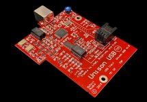
Could this be adapted to your needs? It's a usb input from schiit made as an upgrade board for their other products. Maybe you can adapt/hack it to your needs. I think the picture is of an older version
Schiit Audio: Audio Products Designed and Built in California
Could this be adapted to your needs? It's a usb input from schiit made as an upgrade board for their other products. Maybe you can adapt/hack it to your needs. I think the picture is of an older version
Schiit Audio: Audio Products Designed and Built in California
Attachments
So, I need to dig through some threads, read about protocols, and check out boards from the manufacturers you mentioned.
I'm doing some digging through DAC build megathreads, but it's a little overwhelming. I'll keep going.
DIYiggy, are you able to link me to a thread to a DAC that you've built just so I can see an example?
Is I/V typically related to R2R dacs? they're shooting different current through a ladder of resistors and that needs converted to voltage?
The very few I learned - cause most of the technical is above my head- comes fron try & error with tweakings then when I wanted to understand really what happend I readed forums where knowledgeable electrical technicians & engineers.
I followed several DAC project from Diyaudio and I don't see one that can explain you all for a beginning perspective but long hours at reading - it's a hobby - is your best friend.
There is perhaps ine thread which is more didactic than many because it's following an idea to improve a dac design starting from the reference of a DAC chip : Building the ultimate NOS DAC using TDA1541A long read but it embraces many side of what you ask : power supplies topologies, digital front end, analog output designs. Really a gem.
Then reading the datasheets and the wikis of some good electronic companies like Analog Devices helps with a lot of free ressources.
The best is to follow a good dac project thread to beginn to put your hands into it but few threads are complete for all. You can see there are sometimes here a stickys threads on the beginning of each section to read and also wiki section.
I liked a lot for the pedagogy side and good sounding : the one of Jean-Paul member on a little ESS chip -closed project- and a spidf input and the recent one-and still alive- of Miro1360 member where you can make from a to z a dac, author having made the hardest that is pcb boards design and BOM - bill of materials- to buy the parts.
There are of course many others. But those two are an alternativ to a commercial DAC KIT and will sound as good if not better imo.
My 2 cents, many can helps by giving book references and so on. Time and patience to read are your friends. 🙂
Last edited:
Alright so having finished Miro's AD1862 DAC, I feel a little more qualified to answer my original question.
Block chain for a DAC would be:
Conversion to PCM or DSD input ->
OS and lowpass digital filter (not present for NOS, sometimes integrated into newer DS chips) ->
DAC itself ->
I/V conversion circuit (sometimes chips have integrated op amps like the AD1865) ->
Reconstruction filter (buffer with analog low pass)
In common design that's what a DAC is
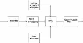
See the attachment for my answer. I treat the current-to-voltage converter (if any) as part of the reconstruction filter, as it is often combined with one or two filter poles.
I've drawn the voltage (or current) and the time references separately, although many DAC chips have them on board. They affect the audio quality, because any imperfections modulate the signal in amplitude and phase.
I've drawn the voltage (or current) and the time references separately, although many DAC chips have them on board. They affect the audio quality, because any imperfections modulate the signal in amplitude and phase.
Attachments
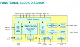
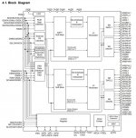
Some alternate views of particular dac chip internal block structures below.
EDIT: Some of the functionality inside such chips may include all or parts of some of the functional blocks as Marcel depicted them. Point is that trying to reduce dacs into typical functional blocks may or may not be useful depending on the intended purpose of the exercise.
EDIT: Some of the functionality inside such chips may include all or parts of some of the functional blocks as Marcel depicted them. Point is that trying to reduce dacs into typical functional blocks may or may not be useful depending on the intended purpose of the exercise.
Attachments
Last edited:
Indeed. I drew my diagram for an article where I needed a block diagram that was as generic as possible and that illustrated the basic digital, analogue and mixed-signal functions. The diagrams Mark posted are meant to show potential customers what is on the chip without giving so much detail that a competitor can copy the design or parts of it.
Keep in mind that designing a four layer circuit board is probably not a task for a beginner, unless you have that under your belt already.
A good way to learn more would be to find a decent kit board and play around with it, maybe to get a fully assembled one also.
I have found them on ebay, however don’t have any to recommend currently.
Honestly, you may well research it for a months before making something, and it may be helpful to have something to use a reference as you go, along with some tools.
- Home
- Source & Line
- Digital Line Level
- DAC block chain and the big picture in DIY DACs?