passive preamp with higher Vrms on the output can have 2 potentiometers in a row, first to set the maximal output voltage (specified as input sensitivity in an end device) and the second potentiometer for full volume control of this device
Thanks but I understood how to calculate the resistor for a desiderate VRMS.
The thing that I don't understand is how to decide this value. If a have a passive preamp which factor I have to take in consideration to decide which vrms is needed? And if I feed directly a power amp?...
you said you had a class A/B 😕
6.4V and 12.8V input to AD1862
Will 6.4V and 12.8V input to AD1862 too high?
and can some coupling caps or resistors can bypass to give pure battery input?
Thanks
Will 6.4V and 12.8V input to AD1862 too high?
and can some coupling caps or resistors can bypass to give pure battery input?
Thanks
That's of course the best way to feed it. The AD1862 is more versatile for that task than the PCM63P cause the digital side is not limited to 5.5/6.0 V.
Best choice of course LiFePo cells. they are 3.3V at their max but show very fastly 3.2 V into load, at least the genuine A123 brand I have. To be a noticeable improvment the LiFePo cells must be directly connected on the load without regs in between. the length of wires must be the shortest possible and the 2 wires wounded : ask a little 3D upon the board diy and creativity 😀.
So two serie LiFePo4 give 6.6 V max for the digital side : perfect !
And 4 in serie, ait I do the math... suspense.... : 13.2 V.
Now it's possible it will ask for a short decoupling on the power pins of the ad1862 : 0.01 uF ; 0.1 uF ; or 1 uF ??? : jusst avoid X7R caps - my personal subjective biased choice my ears thank- Try instead 2.5 mm pitch cap : mkt,mkp or smd NPO or paired SMD PPS 5% precision or less if exist - for this last: my personal biased etc- ....- @ JosephK: oh the japonese AK9099 guys did that also 😉 -
Only a scope measurment could tell if deoupling is needed here or a trade off choice made by listening if no scope imho according how it distors best for our ears. Anyway the real improvment here should come from a I2S front end alsopower fed by the cells and a ground breaker between the data source -playback- and the I2S input.
The temperature climbs with my diy fever and about the opa choice, I'm more and more attracted by adapting the opa 861(that means no headphones if no further buffer) or a Jfet 1556 from Ti or 8610... maybe the opa210... but without being tech and re read some post the feedback oaps sucks for I/V cause linearity... but the opa 861 that is the ideal oap, the rest are mostly good because also their buffer quality in that one oap design we tal about in the thread. However that's theory and ears don't care : the 1556 from Ti -double channel that has not really same spec in single channel, but has a non audio cunterpart in the TI catalog iir- which is not bipolar as the opa861 but Jfet and transimpedance vs transconductance shown subjective good critics in I/V purpose... the numbers are so low perhaps the ears are not ensible anymore...
the LM6176 seems ideal caue very fast and ideal to load headphones- but my understanding after some readings is in I/V its current imput sensisivity copes bad ith a low current output dac cause it's creating instability that seems less terrible with a discrete diamond stage as the Painkiller DAC made for the AD1862 on a discrete design published by P.Rodgic. Btw because the TDA1541A +/- outputt curent there is in the AYAs design of Pedja Rogic a discrete JFET as CCS before the opa861, and my very basic understanding that is not technical is also it is contributing to the gound sound of the opa861 in his design 🙂
BiFet could be cool... wait, they are opa627 😉 AD797 (can be used with no external feedback?)....
Time to make the BOM at Mouser, I waited answers of the FifoPi tweak thread in the PC forums 2 days ago about a BOM cause I have few time to read it, but had no answers - = RTFM 😀 - I only purchase some supercaps too and some more PPS caps from Rubycon that comes in several uF values 🙂
Vishay Roe for the mkp - personal choice - and 2.5 mm ptch MKT from Wima.
Sorry to be a little late for the populating- but summer, sars2 - that's not an oap- ; distanciation- sometimes my laptop is also scarying me... dunno if the cat is chatting at night😀 lol all that are slowling me.
that's cool to have a diy pcb where we can diy around it, thanks Miro1360 again for that.
it should be fine, but count with fully charged battery voltage, not nominal ... lithium batteries are quite dangerous, I wouldn't work with them if I don't know what I'm doing, be careful
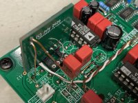
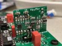
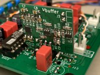
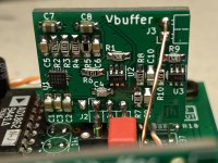
I received the OPA861 I/V output stage boards and built one up to check if it’s a dud or success. I’m happy to say it’s the latter 😀 It works nicely. Thank you jhofland for the pro layout help 🙂
I’ll need to build the second channel to get the full effect.
Details to come.....
I’ll need to build the second channel to get the full effect.
Details to come.....
Attachments
That's rock 🙂 .... But damn where is the opa861 on that pcb ? Is that not a reg ?
Are the 5 pins some discrete buffer arengement ?
Are the 5 pins some discrete buffer arengement ?
Opa861 exist in Soic and SOT23_6..those two are the scheme ~similar Aya, he had even mentioned it.. 🙂
@diyiggy
The opa861 is available in a SOT-23-6 package (6 legs)
These help to keep the pcb size to a minimum.
OPA861IDBVT Texas Instruments | Mouser
U1 is the onboard regulator for 5vdc
The opa861 is available in a SOT-23-6 package (6 legs)
These help to keep the pcb size to a minimum.
OPA861IDBVT Texas Instruments | Mouser
U1 is the onboard regulator for 5vdc
Hello Vunce, how it sounds compared to the classic opamp iv?I received the OPA861 I/V output stage boards and built one up to check if it’s a dud or success. I’m happy to say it’s the latter 😀 It works nicely. Thank you jhofland for the pro layout help 🙂
I’ll need to build the second channel to get the full effect.
Details to come.....
I already have my ad1862 boards build.. just need to buy the components..
[emoji846]
Ah, I got it, there is a thermal pad underneath 🙂
Hey, you should swap the X7R by PPS if you can -Cornell Dublier FCA acrylic, Panasonic PPS or Rubycon PMLCAP-
Do you make the gerber or pcbs avaliable ? And how do you find it vs the other oaps you tried ? What resistor type have you been chosen finally ?
Hey, you should swap the X7R by PPS if you can -Cornell Dublier FCA acrylic, Panasonic PPS or Rubycon PMLCAP-
Do you make the gerber or pcbs avaliable ? And how do you find it vs the other oaps you tried ? What resistor type have you been chosen finally ?
Rather than ordering a batch of PCBs for myself from JLC, is there anyone in Europe with a spare board that they would be prepared to part with. Happy to pay.
Miro. Is there any added problem with the few 1 mA outputt when wiring it to a I/V a liitle farer...inductance and impedance outputt at the ad1862 worsing...tube i/v to manage better the 2 to 3 k ohms outputs...? Was thinking about works of thorsten loesch, Rogic. Jockohomo...dacs works better near the z floor...theoricaaly zero ohms...right?
it can be decreased using thicker and shorter wire -- 10cm wire 1mm diameter has an internal inductance 5nH (10kHz), 20cm wire doubles it ... inductance is small (0.00x) - there will be more on the connector ... but a return current flow may cause problems, the wiring should be as short as possible, a shielded cable is fine but again a short one with a small capacitance. Wiring with poor capacitance (>100pF) will distort.
Thanks to the kindness of a fellow DIY Audio member this project is now on my to do list...
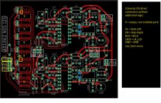
For the digital input I will use a JLSounds i2SoverUSB board and my understanding is that it is capable of processing the 'I2S' data so that it can be connected directly to the digital inputs of the AD1862 chips, negating the need for the shift registers. Is there a header on the PCB to facilitate this - I had a look at the gerber images and I can't see anything so assume not?
For the digital input I will use a JLSounds i2SoverUSB board and my understanding is that it is capable of processing the 'I2S' data so that it can be connected directly to the digital inputs of the AD1862 chips, negating the need for the shift registers. Is there a header on the PCB to facilitate this - I had a look at the gerber images and I can't see anything so assume not?
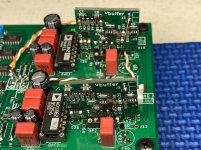
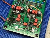
I’ve installed both OPA861 I/V output stage boards and have been listening for the past few days. I am pleased with the results! The improvement I’ve noticed over the opamps I’ve tried is a slightly better soundstage and image. It’s a subtle difference, but worthwhile IMO.
Attachments
...
For the digital input I will use a JLSounds i2SoverUSB board and my understanding is that it is capable of processing the 'I2S' data so that it can be connected directly to the digital inputs of the AD1862 chips, negating the need for the shift registers. Is there a header on the PCB to facilitate this - I had a look at the gerber images and I can't see anything so assume not?
There is not header for direct connection of JLSounds I2S, but you can connect it easily based on this picture ... use shorter wires and configure JLSounds board as written in the manual 🙂
Attachments
I’ve installed both OPA861 I/V output stage boards and have been listening for the past few days. I am pleased with the results! The improvement I’ve noticed over the opamps I’ve tried is a slightly better soundstage and image. It’s a subtle difference, but worthwhile IMO.
thanks Vunce for testing this and detailed progress, so we know another good thing 🙂
Last edited:
There is not header for direct connection of JLSounds I2S, but you can connect it easily based on this picture ... use shorter wires and configure JLSounds board as written in the manual 🙂
Thank you, that is what I had assumed but it's good to confirm. Appreciated

- Home
- Source & Line
- Digital Line Level
- DAC AD1862: Almost THT, I2S input, NOS, R-2R
