Also tried to use the Sjostrom Diamond buffers but there was too much DC, need to work it out.
Them doing what?
@analog_sa Hey I like your bug built CENs, is it a stripped back version without the mosfets? Having them on the DIP adapters is very handy - Patrick showed his CEN circuit on small DIP boards. I may ask Prasi if he could do the same. It would be nice to design a single PCB with the DAC chips and CEN circuit all built in. I really like the CENs with the PCM63. Try the Dark iv if you have a chance to maybe borrow one.
Info here - https://sjostromaudio.com/pages/ind...roem-super-buffer-diamond-buffer-free-samples
I see that Pers Sjostrom has designed a new super buffer, these might be good to try, they are single channel -
https://sjostromaudio.net/shop/built-and-tested-products/61-ssb02-sjoestroem-super-buffer-built.html
You mean what are the diamond buffers doing? well they are single channel op-amps so thought they should work. I used them on a voltage out R2R DAC ok. They are excellent on the output to a Muses Attenuator like Meldano's.Them doing what?
Info here - https://sjostromaudio.com/pages/ind...roem-super-buffer-diamond-buffer-free-samples
I see that Pers Sjostrom has designed a new super buffer, these might be good to try, they are single channel -
https://sjostromaudio.net/shop/built-and-tested-products/61-ssb02-sjoestroem-super-buffer-built.html
The CEN IV shown earlier is the original version published at Linear Audio.
It has very low distortion by design principle.
But a lot of people have 50Hz problems with the floating supplies, unless you use batteries.
It also has a high output impedance, equal to Riv.
https://www.diyaudio.com/community/...lution-of-a-minimalistic-iv-converter.195483/
The FC CEN was designed to overcome that, at the expense of complicity.
Patrick
Patrick showed his CEN circuit on small DIP boards. I may ask Prasi if he could do the same.
a) Have you asked whether I agree to that ?
b) Do you know what components were used ?
c) You can get those unobtainium input JFETs ?
The SMD FC CEN was so difficult that the GB was eventually not a kit, but all built and tested by Fran and me.
https://www.diyaudio.com/community/threads/gb-for-limited-edition-smd-folded-cascode-cen-iv.390857/
It took Fran 3 weeks to learn to build one.
We are not going to do that again.
So those lucky guys are the only ones to have them.
Patrick
Last edited:
The CEN IV shown earlier is the original version published at Linear Audio.
It has very low distortion by design principle.
But a lot of people have 50Hz problems with the floating supplies, unless you use batteries.
I used a separate transformer with two 15v AC windings, half wave rectification, 1000uF and two x 317 regulators set to around 17v. Fets matched only by Idss. Not a hint of hum or noise.
The result is so good i see little point in a more ambitious regulator. Will take some measurements once i get back from a short holiday.
Not my first fet i/v. Ten or so years ago built Owen's single transistor per phase 9018 convertor (fet works at Vds 25v,150mA) which achieved very low distortion by brute force and was, by nature, more fussy towards the coupling caps.
Idss match determines input offset.
Power supply regulation is not critical.
That is the beauty of this circuit.
If you understand how it functions.
The 50Hz problems depends on placement of transformers as well as many other things.
So my congratulations to you for a successful implementation. 😉
Patrick
Power supply regulation is not critical.
That is the beauty of this circuit.
If you understand how it functions.
The 50Hz problems depends on placement of transformers as well as many other things.
So my congratulations to you for a successful implementation. 😉
Patrick

The FC CEN was designed to overcome that, at the expense of complicity.
Patrick
Indeed this complicity with woodturner-Fran expensed !


Anyone with some basic understanding of electronics would have no difficulties building the through hole version.
How the circuit functions have been explained in great detail.
The SMD version is more complex because of size and component limitations.
And the fact that basic precautions against electrostatics were not observed reflects the technical level today, especially in analogue electronics, compared to e.g. a decade ago.
Patrick
@ Patrick , what is the technical level today ?? , from your point of view , obviously.....
a) Have you asked whether I agree to that ?
b) Do you know what components were used ?
c) You can get those unobtainium input JFETs ?
a) are you here for sharing or asking for some glory ??
B) they will find them , people are that stupid ...
c) as you did they will
.
a) Have you asked whether I agree to that ?
b) Do you know what components were used ?
c) You can get those unobtainium input JFETs ?
a) are you here for sharing or asking for some glory ??
B) they will find them , people are that stupid ...
c) as you did they will
.
Last edited:
You mean what are the diamond buffers doing? well they are single channel op-amps so thought they should work. I used them on a voltage out R2R DAC ok.
Buffers are not opamps and have no utility as an I/V stage. You can certainly use them downstream from an (opamp) I/V stage, which will allow the opamp to work in class A over a wide range of loads.
@EUVL, do you mean the the Mosfet of the THT version are more handy to avoid ESD from the operator ? Or same same fragility than the smd board ?
Anyway that servo at the input to make it work nearer to 0Z input will be hard to figth. The thing that always worry me in such design is not the sonic result that should excell, but the rarity of the Fets and the servicing if any problem. Which should not hurt an enthusiast to cross the path chasing for the good sound.
Anyway that servo at the input to make it work nearer to 0Z input will be hard to figth. The thing that always worry me in such design is not the sonic result that should excell, but the rarity of the Fets and the servicing if any problem. Which should not hurt an enthusiast to cross the path chasing for the good sound.
Last edited:
Buffers are not opamps and have no utility as an I/V stage. You can certainly use them downstream from an (opamp) I/V stage, which will allow the opamp to work in class A over a wide range of loads.
Noted, thanks 👍
@miro1360
Hi dear miro
I have some tda1541 non A and wanted to made your dac
First question:
Does the shift register on this board accept 348khz sampling rate from i2s?
Because up sampling can improve the shape of the signal.
Second question:
Does your VHDL code support 1541 non A?
I2S to simultaneous CPLD TDA1541
Third question:
Is the following method correct for up sampling?
USB TO I2S -> SRC (SRC4192 192k up sampling) -> EPM240 (Convert i2s to simultaneous mode) -> TDA1541
🙏🏻
Attachments
@mehdism
Difference between TDA1541 and TDA1541A is only in capacitor (C15). In the non A version this capacitor is not used. There should not be another differences.
Shift register on the board is not supporting 384 kHz. I am not sure if the CPLD does support, but you can easily try it. If you notice any problems, you can play with LE bits a bit in the code.
This part of the code:
if (cntOB = 17) AND (inLRCK = '0') then -- LE pulse duration (4 BCK)
leFlag <= '1';
elsif (cntOB >= 21) then
leFlag <= '0';
end if;
Make the LE duration longer, maybe try 10 BCK:
if (cntOB = 17) AND (inLRCK = '0') then -- LE pulse duration (10 BCK)
leFlag <= '1';
elsif (cntOB >= 28) then
leFlag <= '0';
end if;
I did not test it, so you can do it 😉
Correct, for upsampling with filter you can do it like this:
USB TO I2S -> SRC (SRC4192 192k up sampling) -> EPM240 (Convert i2s to simultaneous mode) -> TDA1541
Be sure that everything is configured for standard 64fs (BCK) and not 32 or 128 🙂
Short answer : do not focus about that numbers and high frequency clocks (it depends if 32 or 64 conf) with a 16 bit clock.
Longer answer :Have you a lot 384 K hz materials ? Which is the second family speed of rare material reccordings, no !
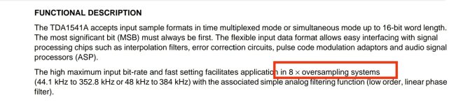
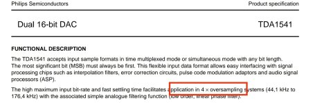
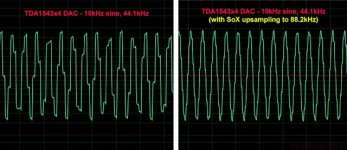
Written differently, many people noticed than x 8 upsampling didn't add vs x4 upsampling. At least with that chip (and most of the old pcm ones)
While it is feasible (P. Rogic demonstrated that) it has no improvment in the real world of your hearing vis à vis of all the (complex) needed things trade offs needed with that chip around (layout - ah that ground with 3 voltages 🙂 ) output stage with its 0 to - 4 mA output and so on (the DEM, the DEM clocking while you are captured with a non A chip)
Notice than if the non A has the cap inside, the pins are still active if you want to follow the nowadays fame that brings nothing essential for the sound but for the hysteric scope measurement people that think their rigth brain can translate a measurement into sound at just looking at THD !
What you could do instead (and that has a sense but the race of the numbers horse) is to to apply to miro pcb's the Grunding DEM that needs x4 upsampling 😉 and that is proof sounding good 😉 (multiple as the nowadays condescending multiple blinkeyes when too much often used)🤣
While hs gnd design is not made for it so not ideal for it, it is worthing to try it and I surmise it will sound better... and then currents will find a path anyway whatever the nonn ideal ones !
Oh, I'm sur some will have some different theorical answers splitting fur in 4 parts, lol !
Longer answer :Have you a lot 384 K hz materials ? Which is the second family speed of rare material reccordings, no !
Written differently, many people noticed than x 8 upsampling didn't add vs x4 upsampling. At least with that chip (and most of the old pcm ones)
While it is feasible (P. Rogic demonstrated that) it has no improvment in the real world of your hearing vis à vis of all the (complex) needed things trade offs needed with that chip around (layout - ah that ground with 3 voltages 🙂 ) output stage with its 0 to - 4 mA output and so on (the DEM, the DEM clocking while you are captured with a non A chip)
Notice than if the non A has the cap inside, the pins are still active if you want to follow the nowadays fame that brings nothing essential for the sound but for the hysteric scope measurement people that think their rigth brain can translate a measurement into sound at just looking at THD !
What you could do instead (and that has a sense but the race of the numbers horse) is to to apply to miro pcb's the Grunding DEM that needs x4 upsampling 😉 and that is proof sounding good 😉 (multiple as the nowadays condescending multiple blinkeyes when too much often used)🤣
While hs gnd design is not made for it so not ideal for it, it is worthing to try it and I surmise it will sound better... and then currents will find a path anyway whatever the nonn ideal ones !
Oh, I'm sur some will have some different theorical answers splitting fur in 4 parts, lol !
Last edited:
@mehdism
Difference between TDA1541 and TDA1541A is only in capacitor (C15). In the non A version this capacitor is not used. There should not be another differences.
🙂
It is used as it is inside and there is great chance it is not trimmed for over than 176 K hz DEM clock decoupling speed but the exact value still has to be confirmed (maybe it was said in the datasheet or the paper for cd players hifi brand designers) as the pre tda1540 DEM cap were a little high values over 860 pF and with the post non R TDA1541A sometimes up to 580 pF and more something for the very few my memory serves nowadays with all that cd players from Philips to Marantz I putted my hands into.
The non R has its charm and does sound not exactly the same while can not deny its family sounding legacy ! 🙂
Last edited:
"Written differently, many people noticed than x 8 upsampling didn't add vs x4 upsampling"
R serie was said to be sorta prototypes... That work very well for a said called prototype !
You should focus, again, on the essential things, if it is related to sounding result.
R serie was said to be sorta prototypes... That work very well for a said called prototype !
You should focus, again, on the essential things, if it is related to sounding result.
Last edited:
x4 vs x8 with TDA1541A... nope, as far hearing music is your goal ! there are better birds to chase with that chip ! Whatever you shpw tda1543 measurements or any 16 bits chips. Going higher frequency has some drawbacks ! At least my long experience with that chip. YMMV. Try blind tests and report, do not stop on datasheets eachtime.
- Home
- Source & Line
- Digital Line Level
- DAC AD1862: Almost THT, I2S input, NOS, R-2R