Best to make or borrow that Quasimodo tester. It is the right thing to do a snubber on the secondary of the transformer that solves it all.
Yes, exactly! I have a Quasimodo.
🙂

I doubt it would have damaged anything, but it would have changed the filter characteristics and it will sound different with them removed.Yes I understand this now. I doubt I can have damaged anything on the dac board by not doing so? . It played music nicely before the swap.
I just finished that tester yesterday and tried it on an old transformer. I'm just wondering if there will be any difference in the sound.Yes, exactly! I have a Quasimodo.
🙂
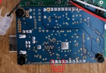
I've had a couple of AD1862 chips hanging around here for a while and I thought I should finally get around to using them. I also have a JLSounds V2 board so decided to make use of it too - I checked the documentation and V3 is backward compatible with V2, so would seem to be suitable;

It was a simple build but unfortunately, so far, not successful as I get a 'white noise' on the outputs. As the noise is the same on both channels my starting assumption is that the issue is before the AD1862 chips - the LRCK and BCLK are common, or perhaps there is a problem with the JLSounds module. I'll get a 'scope onto some trobleshooting tomorrow
Any thoughts in the meantime?
@nautibuoy Did you try this configuration? 🙂
https://www.diyaudio.com/community/...st-tht-i2s-input-nos-r-2r.354078/post-7438473
https://www.diyaudio.com/community/...st-tht-i2s-input-nos-r-2r.354078/post-7438473
Any thoughts in the meantime?
Did You check this :
Nixie :
"At the start, it did not work immediately, because pin 8 on the I2S connector is not connected to GND, even if it is marked as a GND. Connected it from the bottom with pin 7 (also marked as a GND) and now everything is as it should be.
That I2S connector of mine is the same for all DACs (2-4-6-8 pins), so if pin 8 is not on GND, it won't work. Miro said he corrected everything, maybe we used an old gerber file? But all the same, it's nothing dangerous, it just won't work well, it screams."
Post #7,731
It only matters when using I2S and shift registers, and he used a JLS-AD1862 direct connection and another PCB.
But shouldn't that JLS card be turned the other way, so that the cooler and other things are on top? 🤔
But shouldn't that JLS card be turned the other way, so that the cooler and other things are on top? 🤔
JLSounds V2 doesn't have that header. I have R13 populated (4K7).@nautibuoy Did you try this configuration? 🙂
https://www.diyaudio.com/community/...st-tht-i2s-input-nos-r-2r.354078/post-7438473
I should also add that the JLSounds connects to my laptop and 'plays' tracks, so is powered correctly and apparently functioning.
Last edited:
The JLSounds is the correct way round.But shouldn't that JLS card be turned the other way, so that the cooler and other things are on top? 🤔
Just working through the Psu2 Bom and have a couple of questions,
Are the resistors through hole or Smd, if Smd which package?
With Tr3 is it a 100k of 50k trimmer?
Thanks
Are the resistors through hole or Smd, if Smd which package?
With Tr3 is it a 100k of 50k trimmer?
Thanks
Ok.The JLSounds is the correct way round.
White noise is obtained with the wrong I2S connection, but you don't use it. I don't know what it could be.
Finally got a longer weekend between 22nd and 25th December so I decided to complete the work on my TDA1541 DAC, the boards were ready and supply voltages on all major pins of all ICs were checked before inserting the ICs.
All connectors were checked for any disconnection. TDA1541 not the A or R or R2 but simply the 1541 and the specs say it is 5Y. Since finding an authentic TDA1541 is bit of a challenge thus I had decided to salvage the same from old/non-working CD players. I bought these CD players between $5 and $10 depending upon the make and model of the CD player, some of the one that I purchased are as follows:
SONY CDP-750
SONY-CD-950
ARCAM Alpha 5 plus (It was supposed to have 1541A but it actually had the 5Y version)
SONY 333ESD
Phillips CD380
And one TEAC CD-Z500 is on the way (this one is supposed to have dual TDA1541A)
Once I turned on the DAC to my utter dismay first there was no sound with DC Blocking circuit plugged in, after removing the DC Blocking circuit there was sound at the output but with severe distortion. As the 1541 is salvaged it was the first suspect, thus I replaced the entire DAC board with the second one.
Distortion was still there and I had to replace the power supply board but still the same distortion. Replaced Trafo’s, RCA jack and Amanero but the problem did not go away, even replaced Amanero power supply from USB to internal after removing L1, till I decided to change the last suspect which was iPAD and connected the DAC to my laptop. Wallah and it sings.
Conclusion TDA1541 does not like to be driven from an iPAD/USB interface as compared to AD1865 or AD1862. (No idea why?)
Casing is still the old crappy test bed, but hopefully will find a better one soon, may be some CNC Aluminum workshop locally. Already lost two consignments due to disagreements with the customs assessment of taxes.
Once TDA1541 was tested the next stage was to pit the three DACs AD1865, AD1862 and TDA1541 against each other under the same environment. I still couldn’t decide between AD1862 and TDA1541. AD1865 is bit lacking but not so much. I/V was the standard on the boards, OP-AMPs were all OPA627 purchased from TI about 18-20 years ago, all of them are from the same batch.
Made a comparative video (albeit my highly questionable video editing expertise).
BTW: the ILI9341 and PI-PICO are my version of sample rate display which is under testing although its much better than my previous version based upon Arduino, but it still requires some polishing.
Way forward is probably testing my last batch of LME49710 metal can ones and Mr. V’s I/V stage once I complete it.


Here is the link to the youtube video that I made comparing TDA1541, AD1862 and AD1865:
Youtube video
All connectors were checked for any disconnection. TDA1541 not the A or R or R2 but simply the 1541 and the specs say it is 5Y. Since finding an authentic TDA1541 is bit of a challenge thus I had decided to salvage the same from old/non-working CD players. I bought these CD players between $5 and $10 depending upon the make and model of the CD player, some of the one that I purchased are as follows:
SONY CDP-750
SONY-CD-950
ARCAM Alpha 5 plus (It was supposed to have 1541A but it actually had the 5Y version)
SONY 333ESD
Phillips CD380
And one TEAC CD-Z500 is on the way (this one is supposed to have dual TDA1541A)
Once I turned on the DAC to my utter dismay first there was no sound with DC Blocking circuit plugged in, after removing the DC Blocking circuit there was sound at the output but with severe distortion. As the 1541 is salvaged it was the first suspect, thus I replaced the entire DAC board with the second one.
Distortion was still there and I had to replace the power supply board but still the same distortion. Replaced Trafo’s, RCA jack and Amanero but the problem did not go away, even replaced Amanero power supply from USB to internal after removing L1, till I decided to change the last suspect which was iPAD and connected the DAC to my laptop. Wallah and it sings.
Conclusion TDA1541 does not like to be driven from an iPAD/USB interface as compared to AD1865 or AD1862. (No idea why?)
Casing is still the old crappy test bed, but hopefully will find a better one soon, may be some CNC Aluminum workshop locally. Already lost two consignments due to disagreements with the customs assessment of taxes.
Once TDA1541 was tested the next stage was to pit the three DACs AD1865, AD1862 and TDA1541 against each other under the same environment. I still couldn’t decide between AD1862 and TDA1541. AD1865 is bit lacking but not so much. I/V was the standard on the boards, OP-AMPs were all OPA627 purchased from TI about 18-20 years ago, all of them are from the same batch.
Made a comparative video (albeit my highly questionable video editing expertise).
BTW: the ILI9341 and PI-PICO are my version of sample rate display which is under testing although its much better than my previous version based upon Arduino, but it still requires some polishing.
Way forward is probably testing my last batch of LME49710 metal can ones and Mr. V’s I/V stage once I complete it.
Here is the link to the youtube video that I made comparing TDA1541, AD1862 and AD1865:
Youtube video
CineMag CM-10100 on mini wooden plank. Will make more official breakout board and probably enclose in metal can somehow, I’ve got a little bit of ear-to-the-speaker hum if you turn it up all the way, inaudible at normal volumes, steel can will help determine if the hum is induced or a grounding issue.
This setup sounds utterly beguiling. 🙂

This setup sounds utterly beguiling. 🙂
Oh I see, I got the versions wrong ...JLSounds V2 doesn't have that header. I have R13 populated (4K7).
I should also add that the JLSounds connects to my laptop and 'plays' tracks, so is powered correctly and apparently functioning.
R13 is populated + try to add this configuration resistor 😉
Attachments
He has the "flipped" version PCB 😊But shouldn't that JLS card be turned the other way, so that the cooler and other things are on top? 🤔
Yes, I'm going to try that today - I reread the V2 'datasheet' again last evening and had the same thought. Also, my JLSounds V2 is quite old and I'm wondering if it might need a firmware update so I may reach out to them to get some advice if the additional config resistor doesn't do the trick....try to add this configuration resistor 😉
Well, I didn't know about that. 🤣He has the "flipped" version PCB 😊
'flipped board' R13 (4.7k) is on the dac board.

Can you tell us how you did configure the JLSounds board V2? @nautibuoy
I believe there is some jumpers and bridging resistors. i realise i could not find user guide for JLSounds i2sover usb v2 boards anymore.
Can you tell us how you did configure the JLSounds board V2? @nautibuoy
I believe there is some jumpers and bridging resistors. i realise i could not find user guide for JLSounds i2sover usb v2 boards anymore.
- Home
- Source & Line
- Digital Line Level
- DAC AD1862: Almost THT, I2S input, NOS, R-2R