The sacrificial CD player (Sony CDP-207ESD) has arrived and been stripped down. This one has a plain TDA1541, non-A.
It looks from the datasheets like the only implementation difference should be omitting the external capacitor between pins 17 and 18 (C15 on miro's board)?
It looks from the datasheets like the only implementation difference should be omitting the external capacitor between pins 17 and 18 (C15 on miro's board)?

Non-A cannot do Simultaneous Mode, i think.The sacrificial CD player (Sony CDP-207ESD) has arrived and been stripped down. This one has a plain TDA1541, non-A.
It looks from the datasheets like the only implementation difference should be omitting the external capacitor between pins 17 and 18 (C15 on miro's board)?
The datasheets have nearly identical language around mode:
The TDA1541 accepts input sample formats in time multiplexed mode or simultaneous mode with any bit length.
The most significant bit (MSB) must always be first. This flexible input data format allows easy interfacing with signal processing chips such as interpolation filters, error correction circuits, pulse code modulation adaptors and audio signal processors (ASP).
The TDA1541A accepts input sample formats in time multiplexed mode or simultaneous mode up to 16-bit word length.
The most significant bit (MSB) must always be first. The flexible input data format allows easy interfacing with signal processing chips such as interpolation filters, error correction circuits, pulse code modulation adaptors and audio signal processors (ASP).
Oops, sorry for the wrong info above.The datasheets have nearly identical language around mode:
The TDA1541 accepts input sample formats in time multiplexed mode or simultaneous mode with any bit length.
The most significant bit (MSB) must always be first. This flexible input data format allows easy interfacing with signal processing chips such as interpolation filters, error correction circuits, pulse code modulation adaptors and audio signal processors (ASP).
The TDA1541A accepts input sample formats in time multiplexed mode or simultaneous mode up to 16-bit word length.
The most significant bit (MSB) must always be first. The flexible input data format allows easy interfacing with signal processing chips such as interpolation filters, error correction circuits, pulse code modulation adaptors and audio signal processors (ASP).
TDA1541A can be replaced with TDA1541 in the PCB from me 😊 Just the C15 capacitor is omitted 🙂

@Vavilen R4, R5, R6, R7, TR1 and TR2 are optional - only for someone who would like to experimentally set a higher accuracy of DAC, but you have to have some equipment for that (it is inaudible, can be only measured). You should not install these components without further setting and knowledge for setting, because paradoxically you will reduce the default accuracy (factory set). So don't install these components 🙂
It has been a little while since I wrote about trying different AD opamps in post #4742. I finally got to burn in the Burson V6V. As expected, after breaking in, they smoothed out a little and opened up a little more. Going back to the AD797, which I previously liked best, I have to say I do find the 6V6 discreet opamp a little clearer throughout the whole frequency range. I did not notice anything objectionable added. This may be subjective, but I did like all my recordings a little better, although it was not a huge improvement, but definitely noticeable. I began to wonder just how good miro's DAC could sound trying out discrete opamps. The only problem is the discrete opamps, like the 6V6 cost more than most opamps, so I personally cannot try out every type of discrete opamp. However, a few people wrote that they really liked the Sparkos SS3601, so I am burning in a pair of Sparkos now. Maybe soon, I will be able to write my subjective opinion on what I think of those compared to the Burson. I am thinking that might be helpful to anyone else thinking about opamp rolling. Notice I attached some of the components (near the DIP8 sockets) on the underside of the pcb to make room for large opamps.

It is possible that they are very similar in terms of sound, I mean SS3601 and V6 Vivid single. The V6 Classic sounds a little different than the SS3601. I can live happily with any of those. We are here in the zone of small differences. 😊
All done (except for heatsing for jlsounds xmos +5v ldo, debating if i should go larger). Man i love black pcbs 😁
Jlsounds board and toroid transformers are incoming in a week or two, so i'll put it to work asap 💪🏻

Jlsounds board and toroid transformers are incoming in a week or two, so i'll put it to work asap 💪🏻
Beauty!All done (except for heatsing for jlsounds xmos +5v ldo, debating if i should go larger). Man i love black pcbs 😁
Jlsounds board and toroid transformers are incoming in a week or two, so i'll put it to work asap 💪🏻
View attachment 1107580
Could you please share why do you need so many PSUs? One more is for jlsounds?
😊Beauty!
Could you please share why do you need so many PSUs? One more is for jlsounds?
Yeah one is for xmos chip for jlsounds (to the far right, it is the most mA). First board from left is +-12v for opamps. +-5v for analog. Next board -+5v for digital. Remaining +5v on it is also for jlsounds board.
For the JLS XMOS part and the required 400mA 5V, a solid size cooler is needed. Or sacrifice the resistor in the CRC and drop the voltage on it so that a large heatsink is not needed.
the non-A version has its multi vibrator oscillator with the cap inside... the value is certainly something betwwen the 470 pF to 580 pF.The sacrificial CD player (Sony CDP-207ESD) has arrived and been stripped down. This one has a plain TDA1541, non-A.
It looks from the datasheets like the only implementation difference should be omitting the external capacitor between pins 17 and 18 (C15 on miro's board)?
But it is interresting to notice the two pins are still connected, so you can // cap if you want to play with the DEM decoupling 14 caps.
By increasing the cap value between pin 17 & 18 you get a lower DEM frequency. The classic 470 pF to 860 pF gives 200 K hz to 100 K hz if I am correct and it is just fine, imo !
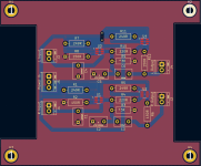
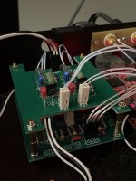
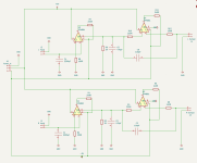
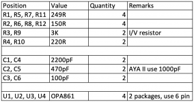
I was playing with different I/V resistors, it was fun. Then, I came across @Vunce's OPA861 I/V build #1417. I want to make a set but realised the SMD soldering of the TPS7A39 is not an easy task. Taking it as an adventure and learning process, I took Vunce's schematic to draw a through hole version board using KiCAD.
Attachments
Super job creating a through-hole version, Crymen! The WSON-10 smd TPS7A39 package in not easy to solder.
Pedja Rogic is the designer of this circuit and deserves all the credit for this excellent I/V output stage.

Pedja Rogic is the designer of this circuit and deserves all the credit for this excellent I/V output stage.
- Home
- Source & Line
- Digital Line Level
- DAC AD1862: Almost THT, I2S input, NOS, R-2R