Hi all,
I know we have another D1 I/V thread.
Just want to separate this as D1 "JFET" I/V. . .
I believe PaPa will encourage us with this.
I also invite all of your opinions, advices and contributions with
your own idea or design.
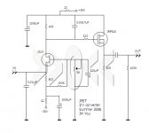
Including the two compensation caps, I am trying to apply the
original component values, except in the area around J310.
I am using J310 as I have many left-over behind my previous
JFET pre project, Krazy.
As you see, this is for the unbalanced output.
I might lower the rail voltages and accordingly scale down other values, later when I actually build.
Will this work. . . ? Thanks for any comment. . .
I know we have another D1 I/V thread.
Just want to separate this as D1 "JFET" I/V. . .
I believe PaPa will encourage us with this.
I also invite all of your opinions, advices and contributions with
your own idea or design.
Including the two compensation caps, I am trying to apply the
original component values, except in the area around J310.
I am using J310 as I have many left-over behind my previous
JFET pre project, Krazy.
As you see, this is for the unbalanced output.
I might lower the rail voltages and accordingly scale down other values, later when I actually build.
Will this work. . . ? Thanks for any comment. . .
Attachments
Ayo. . . 
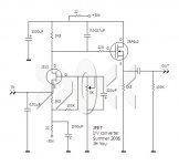
Found one mis-print.
Corrected and marked it in red - i.e. reversed polarity of the electrolytic cap at the bottom.
As the reversed polarity causes unsafe explosion of the cap,
I would like to ask Audiofreak to remove the drawing in post#1.
Thanks.
Found one mis-print.
Corrected and marked it in red - i.e. reversed polarity of the electrolytic cap at the bottom.
As the reversed polarity causes unsafe explosion of the cap,
I would like to ask Audiofreak to remove the drawing in post#1.
Thanks.
Attachments

Thanks, Pa Pa, for the positive comment. 😀
🙂 🙁 🙂 🙁 . . .
I do not know when . . .
Our customers ask tech meetings on Saturday and Sunday . . .
🙂 🙁 🙂 🙁 . . .
I do not know when . . .
Our customers ask tech meetings on Saturday and Sunday . . .
To build this, I wanted to see inside of my CD-player
Hek! found that the output of DAC was voltage, not current
What should I do? Still can go ahead?
Hek! found that the output of DAC was voltage, not current
What should I do? Still can go ahead?
Looking at the schematics it looks as if this DACchip has no I-out - I dont know if theres anything you can do..... My AD1865 has pins where you can tap the I signal and not send it to the internal opamps - looks like the 1732 does not give you this option.....
Cheers !
Hans
Cheers !
Hans
buy some older Philips junkBabowana said:To build this, I wanted to see inside of my CD-player
Hek! found that the output of DAC was voltage, not current
What should I do? Still can go ahead?
I'm full of them 😉 even if some aren't in my place.....
it's time to have more than few CD players,isn't it?
except if you are in new technologies ,as DVD or something.....
btw-when you'll try toob susy?
Maybe what you need is a nice J-fet buffer, without the I/V conversion, after the DAC-chip then? Might be better than the ugly opamps. Something with balanced output would be nice. I wouldnt know, just throwing out an idea🙂found that the output of DAC was voltage, not current
Steen🙂
Buhl said:looks like the 1732 does not give you this option.....
Cheers !
Hans
Cheers!!! 😀
Choky said:buy some older Philips junk
it's time to have more than few CD players,isn't it?
except if you are in new technologies ,as DVD or something.....
btw-when you'll try toob susy?
Will try to find one
Have number of CDs, no need DVD/SACD
Time not allow my thinking back to tubes
But who knows 😀
steenoe said:Maybe what you need is a nice J-fet buffer, without the I/V conversion,
Steen🙂
Tube buffer after the PCM1732
Ah, the sound sour for me
Jfet/Mosfet buffer, good idea 😀
Thank you all
- Status
- Not open for further replies.
- Home
- Amplifiers
- Pass Labs
- D1 - JFET I/V Converter