Hello,
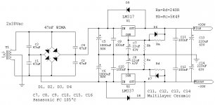
for power supply with LM317 I use the following
In place of RA, Rb, Rc and Rd use 2 trimmers to set the voltage correctly. I think that Rb and Rc shouldn´t be exactly the same or you dont get the voltages matched all the time.
Parts dont give symmetric voltage.
for power supply with LM317 I use the following
In place of RA, Rb, Rc and Rd use 2 trimmers to set the voltage correctly. I think that Rb and Rc shouldn´t be exactly the same or you dont get the voltages matched all the time.
Parts dont give symmetric voltage.
Attachments
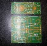
This is the PSU.
I didnt change much.
Made some pads bigger for better soldering.
The holes are now correct for the parts with thick terminals.
There are 2 more holes for bigger caps.
10uF MCap from Mundorf can be used on the board.
The Ground track is corrected.
I didnt change much.
Made some pads bigger for better soldering.
The holes are now correct for the parts with thick terminals.
There are 2 more holes for bigger caps.
10uF MCap from Mundorf can be used on the board.
The Ground track is corrected.
Attachments
No commercial use.
That's for sure. I doubt Nelson Pass would want that Pass Labs designs be used for others to make money anyways.
I forgot to mention: it would be that, once my DAC will be done, I'll create a web page with all schematics, PCBs(Layouts, not for sale), and without forgetting credits to people like you and many others and links to the posts.
So, I'd write:
I/V stage PCB designed by Promitheus from the Pass Labs D1 design. See http://www.diyaudio.com/forums/showthread.php?threadid=30208
DragonMaster how is your DAC going along?
For those who have ordered PCBs, I will get them next week.
I will post more info and photos when I get them.
For those who have ordered PCBs, I will get them next week.
I will post more info and photos when I get them.
Not going pretty far. There's so much parts to select and only 60 hours of Internet per month so it's practically impossible to make a list.
For the resistors and caps, I still have to make the choice between Xicon and Panasonic. Maybe I'll use drops in the I/V stage.
I don't want to spend tons of on them as I will build more than one and money is not coming in very fast.
I at least now selected what I will use to build it.
Pedja Rogic DAC + SPDIF part,
TNT Audio PSU,
74HC157 input switch,
D1 I/V stage,
cm's EIAJ to I2S converter(If I need it),
PCM2706 USB input,
maybe others I forgot.
I just need to find which resistors are going around the TL431 I'll use to power the 74HC157.
An other problem, batteries or tranny.
For the resistors and caps, I still have to make the choice between Xicon and Panasonic. Maybe I'll use drops in the I/V stage.
I don't want to spend tons of
on them as I will build more than one and money is not coming in very fast.I at least now selected what I will use to build it.
Pedja Rogic DAC + SPDIF part,
TNT Audio PSU,
74HC157 input switch,
D1 I/V stage,
cm's EIAJ to I2S converter(If I need it),
PCM2706 USB input,
maybe others I forgot.
I just need to find which resistors are going around the TL431 I'll use to power the 74HC157.
An other problem, batteries or tranny.
It seems to me that you gentlemen are ready to apply the
new power JFETs to a D1 style I/V. Which of you is going to
do it?
😎
new power JFETs to a D1 style I/V. Which of you is going to
do it?
😎
Me when I'll finally finish and order a parts list. (It's surely not tomorrow that it will happen)
Me when I'll finally finish and order a parts list.
Not ... I'll stick with what has been done.
Hey, your Ra to Rd are not placed for multiturns...
Btw, what value are the multiturns? The nearest is 5k.
Hi, I was trying to make a parts list for the PSU. The scheme and parts list are not telling the same thing.
First, in the parts list, there are no 47nF while in the scheme there are. In the scheme, you call some 220uF electrolytics some multiceramics.
Other things like this are on it. That's the other kind of problem I encounter when trying to do a parts list.
First, in the parts list, there are no 47nF while in the scheme there are. In the scheme, you call some 220uF electrolytics some multiceramics.
Other things like this are on it. That's the other kind of problem I encounter when trying to do a parts list.
DragonMaster
Ra to Rd are normal resistors.
The tip to use multiturn resistors was if you make it yourself.
47n are the caps across the diodes in the bridge.
the multilayer are 100n across the input and output of the ICs.
Ra to Rd are normal resistors.
The tip to use multiturn resistors was if you make it yourself.
47n are the caps across the diodes in the bridge.
the multilayer are 100n across the input and output of the ICs.
47n are the caps across the diodes in the bridge.
the multilayer are 100n across the input and output of the ICs.
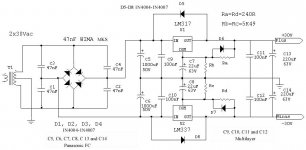
That doesn't tell me why some 220µF caps are listed as multilayer ceramics in d1psulowres.jpg
ok now I found it
C9, C10, C11 and C12 are multilayer
and C5, C6, C7, C8, C13 and C14 are Panasonic FC.
I will get a new schematic uploaded.
C9, C10, C11 and C12 are multilayer
and C5, C6, C7, C8, C13 and C14 are Panasonic FC.
I will get a new schematic uploaded.
Nelson Pass said:It seems to me that you gentlemen are ready to apply the
new power JFETs to a D1 style I/V. Which of you is going to
do it?
😎
Are said Lovoltech FETs sourceable by mere mortals as of yet?
 If so I would be willing.
- Status
- Not open for further replies.
- Home
- Amplifiers
- Pass Labs
- D1 I/V Stage Finished.