I assumed that the node at C5 + and the B+ would be a fairly straightforward implementation.
This is less complicated than the Maida

This is less complicated than the Maida
No, see my remarks in #3200. In addition, this node is low impedance, due to the conduction of the zeners, and this will shunt the correction to GNDI assumed that the node at C5 + and the B+ would be a fairly straightforward implementation.

Made a LM317 Dienoiser addon board and measured it. Had these values:

BJTs were BC8x7-25 gain. I could get away with C6 as ceramic but that didn't work for LM337 dienoiser, so use electrolytic for all C3/C5/C6 (for LM317, just to make sure).
R8 should be 150R-220R. Adjust R4 to have 5-8V on U3 emitter.
Comp cap 47nF.
LM317 made by ST.
Seemed pretty stable. I could get it to go wild if I poked at it under load, repeatedly, it would eventually go crazy but would fast recover once I stopped. Lower gain version is more solid than this but this seems usable.
I powered the LM317 board with addon with my bench switching supply for a more real world scenario, no batteries for these measurements.
155nV total noise:

147dB PSRR at 120Hz:

113.5dB PSRR at 20kHz:

While trying to measure output impedance I realized it's quite important to have LNA sensing right where the denoiser is sensing. And I mean RIGHT in that exact spot. A few mm of trace or even solder would increase it. So I soldered the LNA coax right on the denoiser sensing points.

This is with 33mA RMS current draw. So at 70Hz-500Hz it comes out at around 6uOhms.
I tried LM337 dienoiser addon but it's not very stable. I could get some nice measurements but I can easily make it go off. I'll try to see if I can find a more stable configuration but confidence is low for LM337.
Addon board had sensing wires about 3cm long and ADJ wire some 5cm long.
Tested a few output caps, worked with anything 100-220uF with 0.15-0.2R ESR.
edit: R1 was 2.7K for these measurements. Didn't use 3.3K out of laziness. The 2.7K one was already installed and R2=22K worked nice for ~12Vout. R1 at 3.3K makes for 28.5K for R2 (for 12Vout) which isn't as convenient.
BJTs were BC8x7-25 gain. I could get away with C6 as ceramic but that didn't work for LM337 dienoiser, so use electrolytic for all C3/C5/C6 (for LM317, just to make sure).
R8 should be 150R-220R. Adjust R4 to have 5-8V on U3 emitter.
Comp cap 47nF.
LM317 made by ST.
Seemed pretty stable. I could get it to go wild if I poked at it under load, repeatedly, it would eventually go crazy but would fast recover once I stopped. Lower gain version is more solid than this but this seems usable.
I powered the LM317 board with addon with my bench switching supply for a more real world scenario, no batteries for these measurements.
155nV total noise:
147dB PSRR at 120Hz:
113.5dB PSRR at 20kHz:
While trying to measure output impedance I realized it's quite important to have LNA sensing right where the denoiser is sensing. And I mean RIGHT in that exact spot. A few mm of trace or even solder would increase it. So I soldered the LNA coax right on the denoiser sensing points.
This is with 33mA RMS current draw. So at 70Hz-500Hz it comes out at around 6uOhms.
I tried LM337 dienoiser addon but it's not very stable. I could get some nice measurements but I can easily make it go off. I'll try to see if I can find a more stable configuration but confidence is low for LM337.
Addon board had sensing wires about 3cm long and ADJ wire some 5cm long.
Tested a few output caps, worked with anything 100-220uF with 0.15-0.2R ESR.
edit: R1 was 2.7K for these measurements. Didn't use 3.3K out of laziness. The 2.7K one was already installed and R2=22K worked nice for ~12Vout. R1 at 3.3K makes for 28.5K for R2 (for 12Vout) which isn't as convenient.
Last edited:
I'm thinking of updating the PCB designs with remote sensing. There's no way output impedance doesn't degrade with sensing at output connector.
One detail I read in some LM317 datasheet, can't remember which, was that while it's important R1 senses Vout right at LM317 pin, GND connection for R2 can be at load and was actually recommended, for better regulation or something like that.
In last PCB design I posted, GND for R2 was on denoiser circuit GND sensing point. Should it stay there for remote GND sensing for LM317 R2? If I add remote sensing wire connections on the PCB? Anyone experimented with load ground sensing for R2?

edit: or maybe the best approach would be a set of LM3x7 regular supply PCB + addon board for remote sensing. And PS board would have bottom of R2 for GND + ADJ connections for remote wires from addon. And would a coax work for this job? Bottom of R2 connected to shield and ADJ signal on center wire, from remote addon board?
2nd edit: and is R2 required next to LM317? Can it be on addon board at load?
One detail I read in some LM317 datasheet, can't remember which, was that while it's important R1 senses Vout right at LM317 pin, GND connection for R2 can be at load and was actually recommended, for better regulation or something like that.
In last PCB design I posted, GND for R2 was on denoiser circuit GND sensing point. Should it stay there for remote GND sensing for LM317 R2? If I add remote sensing wire connections on the PCB? Anyone experimented with load ground sensing for R2?
edit: or maybe the best approach would be a set of LM3x7 regular supply PCB + addon board for remote sensing. And PS board would have bottom of R2 for GND + ADJ connections for remote wires from addon. And would a coax work for this job? Bottom of R2 connected to shield and ADJ signal on center wire, from remote addon board?
2nd edit: and is R2 required next to LM317? Can it be on addon board at load?
Last edited:
I have not tested longer runs of wire, just a few cm.
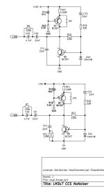
That is the Denoisator, this is the Dienoiser with an extra BJT, higher gain, LM337 is not so stable in this configuration. At least with the values I tried so far.
That is the Denoisator, this is the Dienoiser with an extra BJT, higher gain, LM337 is not so stable in this configuration. At least with the values I tried so far.
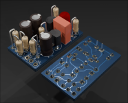
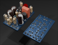
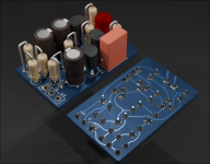
I designed a set of compact THT addon boards, for both LM3x7 Denoisator and one for LM317 Dienoiser. They also have space for two resistors in parallel for R2, they are not required. LM337 one has an extra resistor for comp network.
The higher gain version can be made into a Denoisator by omitting the extra BJT and shorting the 150R-220R resistor.
If you don't like the visible light you can use an IR LED instead. Should work with any color LED in theory, as long as the CCS has the headroom.
Archives contain Kicad project files, PDFs for schematic and DIY and gerbers for fab house. All traces on bottom side.
I have not tested these so you make them at your own risk.
Attachments
No, they are Denoisator addons. In that post you linked I said I tested them on an older NoNoiser PCB I made, I just installed LM3x7 and R1/R2 on it, omitted everything else, and used the Denoisator addons on that PCB.
In this round of testing I didn't test any NoNoiser topology, my goal with increased R1/R2 was to get closer to NoNoiser performance levels without adding the extra BJT of NoNoiser to ADJ pin.
In this round of testing I didn't test any NoNoiser topology, my goal with increased R1/R2 was to get closer to NoNoiser performance levels without adding the extra BJT of NoNoiser to ADJ pin.
Ok, sorry if I misinterpreted what you said. The written name confused me.
Both 317 & 337 measured good and with not instabilities or weird things on the 337 with parts shown?
Both 317 & 337 measured good and with not instabilities or weird things on the 337 with parts shown?
As long as you use the recommended values it should work. But can't guarantee anything, as you can imagine addon boards can be installed in all kinds of applications and that depends on the particular layout and extra components. Maybe the power rails have a bunch of small ceramic capacitors bypassing the large output ones, things of this nature could vary the result.
Make sure you use 47nF compensation for LM317 and 47nF+3.9R for LM337. 0.2R ESR output cap for LM317 and 0.15R-0.2R for LM337 (0.1R wasn't as stable). Remove any 100nF ceramics that are in parallel with the output caps, next to them.
Make sure you use 47nF compensation for LM317 and 47nF+3.9R for LM337. 0.2R ESR output cap for LM317 and 0.15R-0.2R for LM337 (0.1R wasn't as stable). Remove any 100nF ceramics that are in parallel with the output caps, next to them.
Ceramics should be the first thing I would remove or not use on my projects. On any position.
And it seems low ESR caps are not good for 47n capacitor and for output ones.
And it seems low ESR caps are not good for 47n capacitor and for output ones.
Good day, guys:
Can someone share the LTspice CODE of LM317&LM337,or LM7818 & LM7918 ? or spice code is ok, Thank you very much.
Can someone share the LTspice CODE of LM317&LM337,or LM7818 & LM7918 ? or spice code is ok, Thank you very much.
- Home
- Amplifiers
- Power Supplies
- D-Noizator: a magic active noise canceller to retrofit & upgrade any 317-based VReg