Ok, time for another set of measurements.
While I was servicing my Revox B77 reel-to-reel tape machine I noticed the LM317 supply and it dawned on me that I just have to try the denoiser (as they say "when you have a hammer everything looks like a nail" or "when you have a denoiser everything looks like a LM317 power supply") 😀 For all of you already rolling on the floor laughing this is just a technical experiment. I do not claim that reel-to-reel tape would benefit from a denoiser 😀
The measurement setup is the same as earlier (60dB LNA with MAudio ProFire 610 soundcard).
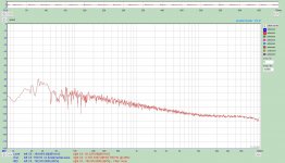
1. Baseline (regular B77 supply i.e. LM317 with Cadj)
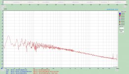
2. Without Cadj. Noise is significantly higher.
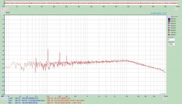
3. With add-on denoiser (single BJT). Nothing to write home about, slightly lower noise above 10 kHz.
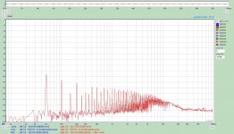
4. Add-on denoiser with sense wires attached to B77 mainboard. Much lower noise floor. The spikes seem to be 50/100hz related. These may be very difficult to eliminate considering the layout of the B77.
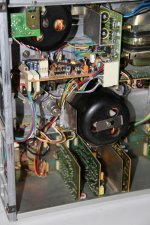
5. Picture of the B77 internals. Denoiser can be seen next to fuses. As can be seen the environment is quite hostile. Power supply board (and the denoiser) sits attached to the main power transformer surrounded by lots of motors, relays and solenoids.
I guess the moral of the story is that add-on denoisers without sense wires may not perform as expected. And even with sense wires the results may not look as pretty as in simulations. And before anybody asks, I do not have anything to say about the sound before or after 😀
While I was servicing my Revox B77 reel-to-reel tape machine I noticed the LM317 supply and it dawned on me that I just have to try the denoiser (as they say "when you have a hammer everything looks like a nail" or "when you have a denoiser everything looks like a LM317 power supply") 😀 For all of you already rolling on the floor laughing this is just a technical experiment. I do not claim that reel-to-reel tape would benefit from a denoiser 😀
The measurement setup is the same as earlier (60dB LNA with MAudio ProFire 610 soundcard).
1. Baseline (regular B77 supply i.e. LM317 with Cadj)
2. Without Cadj. Noise is significantly higher.
3. With add-on denoiser (single BJT). Nothing to write home about, slightly lower noise above 10 kHz.
4. Add-on denoiser with sense wires attached to B77 mainboard. Much lower noise floor. The spikes seem to be 50/100hz related. These may be very difficult to eliminate considering the layout of the B77.
5. Picture of the B77 internals. Denoiser can be seen next to fuses. As can be seen the environment is quite hostile. Power supply board (and the denoiser) sits attached to the main power transformer surrounded by lots of motors, relays and solenoids.
I guess the moral of the story is that add-on denoisers without sense wires may not perform as expected. And even with sense wires the results may not look as pretty as in simulations. And before anybody asks, I do not have anything to say about the sound before or after 😀
Attachments
Just want to ask... never mind 🙂 For some reason I think you will also try out other regs at that position?!
For some reason I think you will also try out other regs at that position?!
Actually was not planning that. The regulated voltage is 21V so beyond the scope of LT30xx. TPS7A470x might just fit the bill.
OK, just curious. Are that Frako caps in the upper PSU section? If so chances are likely that they are dried out.
Are that Frako caps in the upper PSU section?
Yes those are the original Frako caps. Even after 30+ years of service they measured spot-on. As part of the service I checked most (if not all) elkos. The only one requiring replacing was actually the Cadj cap in the LM317 supply 😀
Regulator in Revox b77
About 6 years ago, I replaced the original regulator with an ALSWR ( a super regulator derivative) along with capacitor upgrades/ changes in the power supply. and many of the boards
Do not have any measurements, but there was a significant improvement in sound quality
About 6 years ago, I replaced the original regulator with an ALSWR ( a super regulator derivative) along with capacitor upgrades/ changes in the power supply. and many of the boards
Do not have any measurements, but there was a significant improvement in sound quality
Ok, time for another set of measurements.
While I was servicing my Revox B77 reel-to-reel tape machine I noticed the LM317 supply and it dawned on me that I just have to try the denoiser (as they say "when you have a hammer everything looks like a nail" or "when you have a denoiser everything looks like a LM317 power supply") 😀 For all of you already rolling on the floor laughing this is just a technical experiment. I do not claim that reel-to-reel tape would benefit from a denoiser 😀
The measurement setup is the same as earlier (60dB LNA with MAudio ProFire 610 soundcard).
1. Baseline (regular B77 supply i.e. LM317 with Cadj)
2. Without Cadj. Noise is significantly higher.
3. With add-on denoiser (single BJT). Nothing to write home about, slightly lower noise above 10 kHz.
4. Add-on denoiser with sense wires attached to B77 mainboard. Much lower noise floor. The spikes seem to be 50/100hz related. These may be very difficult to eliminate considering the layout of the B77.
5. Picture of the B77 internals. Denoiser can be seen next to fuses. As can be seen the environment is quite hostile. Power supply board (and the denoiser) sits attached to the main power transformer surrounded by lots of motors, relays and solenoids.
I guess the moral of the story is that add-on denoisers without sense wires may not perform as expected. And even with sense wires the results may not look as pretty as in simulations. And before anybody asks, I do not have anything to say about the sound before or after 😀
Can you test the same way with a Dienoiser instead?
Thx
About 6 years ago, I replaced the original regulator with an ALSWR ( a super regulator derivative) along with capacitor upgrades/ changes in the power supply. and many of the boards
Do not have any measurements, but there was a significant improvement in sound quality
Since most of the electronics on a B77 are powered from this regulated 21V it is quite possible that improving the regulator has impacts on the sound. However the standard LM317 bypassed regulator does not look too shabby based on the measurements.
Can you test the same way with a Dienoiser instead?
Thx
I don't have a suitable dienoiser ready (i.e. having sense wire capability). It might lower the noise floor further but I doubt it would improve the 50/100hz related spuries.
Can you improve your test setup reduce the 50/100hz spikes example screening the power supply / sense cables?
The denoiser improves key parameters by 30~35dB, BUT as is often the case, your mileage may vary/the devil is in the details:I guess the moral of the story is that add-on denoisers without sense wires may not perform as expected. And even with sense wires the results may not look as pretty as in simulations. And before anybody asks, I do not have anything to say about the sound before or after 😀
If you connect the denoiser directly to the LM317 (negligible wiring length) AND you measure the noise exactly at the same spot, you'll get the advertised performance; if you make the measurement at the point of load, anything could happen: the denoiser has no way to know and correct what happens downstream. The cabling could catch noise on its way, the load itself might introduce pollution, etc.
If you use a Kelvin-like connection, as you tried, it allows in principle the denoiser to sense the nasties directly at POL, but you need to keep a number of things in mind: the denoiser is basically a 35dB amplifier. Any noise caught in the input circuit will thus be amplified and appear at the output of the regulator.
For that reason, it is essential to minimize the input loop area to avoid catching and amplifying magnetic perturbations.
The way to do that is to twist together the hot and GND sense wires (and avoid hotspots, like the vicinity of a transformer).
Secondarily, it is desirable to make that twisted pair follow (broadly) the path of the main supply wires. Failing to do so will create another loop also able to catch disturbances. They won't be amplified 35dB, but if they are large they could contribute to the 50Hz pollution and its harmonics.
Can you improve your test setup reduce the 50/100hz spikes example screening the power supply / sense cables?
The way to do that is to twist together the hot and GND sense wires (and avoid hotspots, like the vicinity of a transformer).
Secondarily, it is desirable to make that twisted pair follow (broadly) the path of the main supply wires.
The sense wiring was a screened cable (i.e. hot and GND on separate wires surrounded by screen grounded only at other end). The path followed more or less the main supply wiring. However the main supply wiring goes through a pair of PCB connectors which may have degraded (oxidized) during the 30+ years.
About 6 years ago, I replaced the original regulator with an ALSWR ( a super regulator derivative) along with capacitor upgrades/ changes in the power supply. and many of the boards
Do not have any measurements, but there was a significant improvement in sound quality
I still would like to read comments here about anyone who compared sound quality between the denoiser or dienoiser with any of the Jung/Didden regulator versions, like the ALSWR, that has very been very much tried by so many.
Eventually I probably will when I build my RIAA preamp, but I would like to know of others who tried that.
I'm in similar position. I'm still checking out thread for a DIY friendly, tested single layer +/- dual rails PCB for center tapped transformers. This is the most common use of analog PSU for line level circuits but not yet one appeared. If I had free time as before, I probably had already done for myself.
Good luck finding single layer PCB designs here on diyAudio. The majority of builders here buy premade PCBs from commercial fabrication houses, rather than etch and drill their own boards. Members here feel that commercial fab houses are acceptably fast (approx 10 day turnaround) and acceptably cheap (approx USD30 for 10 PCBs). These fabs concentrate upon 2-layer and 4-layer board manufacturing, and do not offer any significant discount for single layer boards.
Just for learning purposes, get yourself 25 different price quotes on an imaginary 2-layer PCB whose dimensions are 50mm by 90mm. Visit this website
www.pcbshopper.com
put in the board size, tell it what country you want the boards shipped to, and tell it what currency you would like to use for the purchase. Shazam! It spits out 25 quotes, sorted by price. You may be surprised by the cost and speed.
That’s true Mark, it has never been simpler or cheaper to get professional quality PCBs made.
I confess to taking an almost child-like delight in etching my own boards however, it really is a large part of the fun and challenge of the hobby for me.
I put etching PCBs in the same category as building an Amplifier chassis from sheets of steel or speakers from ply; That is to say a sort of quasi-zen evening activity. 🙂
Actually it doesn't matter single or dual layer pcb as long as these conditions met (even though dual layer is not beneficial for such circuit):
* Dual +/- rails
* Center tapped transformer
* Gerbers available
* Tested
* Dual +/- rails
* Center tapped transformer
* Gerbers available
* Tested
Well, I’m working on such a thing for a project of mine and if I get it right, I’ll post it up.
My experiments so far haven’t been the model of success so far... 😀
My experiments so far haven’t been the model of success so far... 😀
I'm in similar position. I'm still checking out thread for a DIY friendly, tested single layer +/- dual rails PCB for center tapped transformers. This is the most common use of analog PSU for line level circuits but not yet one appeared. If I had free time as before, I probably had already done for myself.
I've just done a 60dB LNA based on a Douglas Self design for moving coil head amp, and has +- rails. It's half wave for convenience, and I use larger caps to compensate for that. I can easily adapt the design for full wave but I don't know what size people want to use for input caps. CLC/CRC, first/second cap sizes etc. I run the ground in the middle and +- rails follow on each side for small loop area. The whole LNA has only two bypass links on the topside, but if only the power section is needed then it won't have any, only bottom traces. I have included a smd fuse on the input on the LNA.

- Home
- Amplifiers
- Power Supplies
- D-Noizator: a magic active noise canceller to retrofit & upgrade any 317-based VReg