You are using an out of date browser. It may not display this or other websites correctly.
You should upgrade or use an alternative browser.
You should upgrade or use an alternative browser.
D-Noizator: a magic active noise canceller to retrofit & upgrade any 317-based V.Reg.
- Thread starter Elvee
- Start date
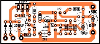
The cross is the place where you can insert a jumper to disable the denoiser, for test or trouble-shooting for example. It is not compulsory of course.Hello Elvee
greetings and thank you for posting the schematic
C3 220uf is it used there is a cross on it
The ZTX is the absolute best, but others come close. You can use a BC337 for example.warm regards
Andrew
ztx 851 any substitute in schematic enclosed
Trileru has tested a number of types, he can probably suggest other substitutes.
Indeed, and the ~constant current through the output transistor could be used elsewhere. Where? I have no idea, probably not in the nonoiser itself, but the circuit it supplies could benefit.
Beware though, not all opto's are IR: some fast types use red, like the 4N<something> for example
Beware though, not all opto's are IR: some fast types use red, like the 4N<something> for example
Yes, the current won't be very predictable/accurate, but it will be reasonably stable and clean, and it will be floating! meaning it can be used anywhere, just like an ideal spice CCS, which can be a great advantage in some circumstances (not for designers who are also real men, capable of dealing with such minor inconveniences in a virile manner of course)
Hi guys,
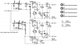
i have this circuit for my COD dac of twisted pear audio, one for analog and one for digital section set to 7.5Vdc. i want to replace this one and i would like to know which one do you suggest?
thank you! Maxpou
http://www.twistedpearaudio.com/digital/cod.aspx
i have this circuit for my COD dac of twisted pear audio, one for analog and one for digital section set to 7.5Vdc. i want to replace this one and i would like to know which one do you suggest?
thank you! Maxpou
http://www.twistedpearaudio.com/digital/cod.aspx
Attachments
Hello Trileru
greetings can the denoisator part be added to a
5 volt 4 ampere linear power supply to reduce noise
warm regards
Andrew
greetings can the denoisator part be added to a
5 volt 4 ampere linear power supply to reduce noise
warm regards
Andrew
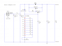
You can connect the output capacitor of a die/denoiser to the base of the transistor. The 2.2µF needs to be removed, and the value of the 220µF can be vastly reduced, according to the values of the voltage divider.Hi guys,
i have this circuit for my COD dac of twisted pear audio, one for analog and one for digital section set to 7.5Vdc. i want to replace this one and i would like to know which one do you suggest?
thank you! Maxpou
http://www.twistedpearaudio.com/digital/cod.aspx
You can also incorporate the transistor in a nonoiser.
You can insert a 470 ohm resistor between the base of the darlington and the diode string, and lift the 220µ from the gnd to use it as coupling cap for a die/dienoiser, but the benefit regarding noise will be small, because it is already quite low.for this schematic
However, it will greatly improve the PSRR and output impedance.
With the more evolved, optimized CCS version of Trileru, the noise will be improved, and the PSRR and Zout will be even better