Evening everyone.
I hear you Elvee,but I went with the resistor before the Leds.Preferring the sound of the latter.This dilemma was easily settled once I removed the Leds this evening and put the resistor back in.
carlmart thank you for the syms.....the Leds need to be flipped as gerhard pointed out.
The idea is from this quote here:
"For 5V output, a useful substitution is to use two green LEDs in series. These will drop about 1.94v each, or 3.9v across the two, with lower impedance than a 3.9v zener - which makes the output voltage setting more accurate, and with lower noise since the leds are forward-biased PN junctions. You also get bright green light to let you know the reg is working..."
I had used LEDs as constant current sources, oriented as diodes. Thought it was the same here.
As the sim worked I thought it was OK. Someone would have to explain to me why the sim did work.
After Gerhard comment I did try the LEDs flipped, and this time I needed two to work fine and output the right voltage. It did work, of course.
PSRR stays around -100dB, a little better with the RC filter trick. That you might try.
Okay carlmart
But I'm at odds with what I hear as opposed to what the sym says.
Indeed Elvee's sym and yours clearly show the superiority of the resistor over the Leds.
I'm stumped.....
But I'm at odds with what I hear as opposed to what the sym says.
Indeed Elvee's sym and yours clearly show the superiority of the resistor over the Leds.
I'm stumped.....
For a non-corrected regulator, the LED mod could be beneficial as it plays ~the same role as Cadj: it shunts the adj terminal to ground, meaning the 317's internal noise is only amplified 1x. (the LED noise is negligible compared to a 317).The idea is from this quote here:
"For 5V output, a useful substitution is to use two green LEDs in series. These will drop about 1.94v each, or 3.9v across the two, with lower impedance than a 3.9v zener - which makes the output voltage setting more accurate, and with lower noise since the leds are forward-biased PN junctions. You also get bright green light to let you know the reg is working..."
It will also defeat any attempt by a denoiser to remove the remainder of the noise.
As soon as you use a correction, the benefit is lost, because even the humblest denoiser version offers >30dB noise reduction over the 317 with Cadj., and this rises to >50dB with the Dienoiser or the nonoiser.
Even with a LED, the Dienoiser will improve the situation by a few dB, but technically speaking, a resistor is far preferable.
If you feel the urge to use an active component there, use a jFET wired as a CCS: it will improve the performance of the denoiser (you will need to select it though).
Okay carlmart
But I'm at odds with what I hear as opposed to what the sym says.
Indeed Elvee's sym and yours clearly show the superiority of the resistor over the Leds.
I'm stumped.....
I think your listening is more important than measurements. You do not listen to specs.
Some prefer the sound of shunt regulators to series regulators. Some do not like regulators at all, just simple CRC or CLC filtering after the diodes.
The only thing I think you should try anyway is adding the resistor before the input filter cap. That would preserve the "LED sound".
There is a slight deterioration between using two green LEDs arranged in series, compared to a resistor. That difference could be around 15 dB approx. in almost all the extension of the audible band, for a nominal output of 5 Vdc and with a RC prefilter (1 ohm and 2200 uF).
Anyway, even with the LEDs instead of a resistor, we get outstanding results compared to the regulator operating alone.
Best regards
Anyway, even with the LEDs instead of a resistor, we get outstanding results compared to the regulator operating alone.
Best regards
I definitely doubt the LT3042 measurements, starting with the missing absolute scale.
My measurements look this way:
(ed. that does not seem to load in finite time)
Circuit is from the data sheet and results are like the data sheet. (red trace)
The strong rise at low frequencies goes on the undersized input capacitor
of the preamplifier. That has been changed in the meantime.
Increasing the output cap of the 3042 beyond the recomendend value creates
a noise peak. (green line). If you insist in a larger cap, you need some damping R.
The other picture is the LT3042 with an external DH44 BJT for large output current.
Also 1:1 from the data sheet.
< spectrum_lt3042_DH44 | Noise spectrum of the LT3042+ D44VH10… | Flickr >
The other pics to the left/right show the noise of some Zeners, LEDs and other references.
All plots are scaled that 0 dB is 1nV/rtHz, which is abt. the equiv. input noise density of an AD797 or LT1028.
Gerhard
Hi Gerhard,
It may be hard to believe, but all my measurements and observations point towards the fact that this little circuit does better than the lt3042.
Now, I was not about to write a spec sheet, so all measurements are relative. I am traveling through the Far East for the next 7 weeks. When I come back, I will first improve my head amp and then redo.
My advice would be: this thing can be built from stuff that any quality nerd has laying around the house. So build one and be amazed.
Get real.
In #495, there is R6 = 47 Ohm in the input of the error amplifier.
That alone guarantees nearly 1nV/rtHz even for an otherwise ideal error amplifier.
The 3042 is definitely at 2nV/rtHz total, there is simply no space left to be much better,
let alone 20 dB as your picture suggests at 50 KHz.
Not even the form of the curve fits.
Last edited:
Morning all
Thanks for the replies.
Elvee so I have J310 somewhere,I'll try your CCS in the LM317 Adj pin.So the Jfet works with the D-Noizator? Not against it.
carlmart thanks for the syms.....why do I keep saying syms when it should be sims?!!!
diegomj1973 thanks and yes I do use an RC filter.
Is anyone actually using Elvee's D-Noizator in their audio setups....please contribute your findings.
I'm using a dual rail version of the original denoiser on a pcb i designed and had fabbed by JLCPCB. ZTX951/851 transistors. LM337/317 ICs.
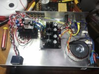
I think I posted the gerber files earlier in the thread if anybody cares to use them.
So far it is built and tested as far as getting into my test rig for a new preamp.
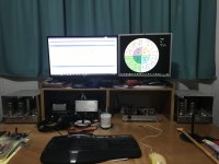
The test rig has just made it into my main system for proper listening tests after burn in. I can say that the preamp sounds damn nice but I cannot say how much the power supply has made an effect as this preamp has not been used with any other power supply. I simply went with what is theoretically the best PSU I could understand and manufacture.
Suffice to say that the circuit works and is stable. At this point I have neither the knowledge or equipment for testing of noise etc.
I can confirm the voltage fluctuation at turn on. The output voltage oscillating on both rails up to about 1V above the designated output voltage.
I recall seeing 16.2v on the positive rail before stabilising at 14.86v and staying rock steady.

I think I posted the gerber files earlier in the thread if anybody cares to use them.
So far it is built and tested as far as getting into my test rig for a new preamp.

The test rig has just made it into my main system for proper listening tests after burn in. I can say that the preamp sounds damn nice but I cannot say how much the power supply has made an effect as this preamp has not been used with any other power supply. I simply went with what is theoretically the best PSU I could understand and manufacture.
Suffice to say that the circuit works and is stable. At this point I have neither the knowledge or equipment for testing of noise etc.
I can confirm the voltage fluctuation at turn on. The output voltage oscillating on both rails up to about 1V above the designated output voltage.
I recall seeing 16.2v on the positive rail before stabilising at 14.86v and staying rock steady.
Get real.
In #495, there is R6 = 47 Ohm in the input of the error amplifier.
That alone guarantees nearly 1nV/rtHz even for an otherwise ideal error amplifier.
The 3042 is definitely at 2nV/rtHz total, there is simply no space left to be much better,
let alone 20 dB as your picture suggests at 50 KHz.
Not even the form of the curve fits.
Build one and come back with your own measurements. Theoretical considerations are nice, but you are rowing in the air without observations.
If you had read the whole thread, you would have known that my 1000 times amp worked as a high pass.
Please, only respond after you did some soldering and measuring yourself.
I'm looking forward to your coming back and repeating all those measurements you did with no high pass.
A CCS will improve the action of the denoiser, but it will also ruin the DC stability of the 317 regulator, and make the voltage adjustment finicky.Morning all
Thanks for the replies.
Elvee so I have J310 somewhere,I'll try your CCS in the LM317 Adj pin.So the Jfet works with the D-Noizator? Not against it
Not something I would recommend, but if you pass half of the tail current through the CCS and the other half through a regular resistor, the circuit will become usable and have performances slightly better than a pure resistor.
Not worth the trouble IMHO.
The denoiser is not limited by the 47 ohm protection resistor: its gain is too low and does not bring the 317's noise in this region.
With the nonoiser and the Dienoiser, things are different: if you use a good input transistor like a ZTX, this resistor will become the major noise source and should be reduced to 22 or even 10 ohm.
Eliminating it completely is tempting, but I don't recommend it: even 10 ohm is better than nothing against mishaps like capacitor charge/discharge
Cheers Elvee....I confess that I hit a brick wall as I looked at the J310 this evening.How in the world is regulated Vdc set with this thing set as a ccs in the Adj. leg of an LM317?
So leave things as is.
Sadface you build the way I can't....very nice!
So leave things as is.
Sadface you build the way I can't....very nice!
Hello,
I have read part of this forum but I have not understood which circuit to try if I wanted to make a low noise dual power supply with LM317 and LM337 .
No one has made a PCB with dimensions and pins compatible with LM317 and LM317 that allows direct replacement?
I saw some drawings in the forum.
Can anyone help me?
Best regards
Guglielmo
Build one and come back with your own measurements. Theoretical considerations are nice, but you are rowing in the air without observations.
If you had read the whole thread, you would have known that my 1000 times amp worked as a high pass.
Please, only respond after you did some soldering and measuring yourself.
At present, of the two of us I'm the only one who has soldered and measured
absolute numbers. And these confirm the AD/LT data sheet at 2 nV/rt Hz.
If you claim to better LT by 20 dB, Hitchen's razor applies. Extraordinary claims
require extraordinary proof. And I did not say that it's impossible.
Show absolute numbers, not two relative traces that could be anything,
and your implementation of the LT has a completely atypical form. There
is no high pass time constant that would allow the rise at a few 100 Hz.
The 3042 is a CCS/Cap lowpass and a follower, and the follower part
has been used by LT after a filtered LT6655 reference to reach even
lower than 2nV/rtHz.
You claim it, you prove it, and not "Go away and don't you dare to come back
without proof of the opposite."
Last edited:
At present, of the two of us I'm the only one who has soldered and measured
absolute numbers. And these confirm the AD/LT data sheet at 2 nV/rt Hz.
If you claim to better LT by 20 dB, Hitchen's razor applies. Extraordinary claims
require extraordinary proof. And I did not say that it's impossible.
Show absolute numbers, not two relative traces that could be anything,
and your implementation of the LT has a completely atypical form. There
is no high pass time constant that would allow the rise at a few 100 Hz.
The 3042 is a CCS/Cap lowpass and a follower, and the follower part
has been used by LT after a filtered LT6655 reference to reach even
lower than 2nV/rtHz.
You claim it, you prove it, and not "Go away and don't you dare to come back
without proof of the opposite."
Sorry, don't you think this sounds a bit aggressive? I hope this could be a cooperative effort. aren't you curious and don't you have an hour to solder this thing together? I am sure you have the parts laying around, I did. Furthermore, comparative measurements are 100% acceptable for an acid test, we are not writing a spec sheet.
Hello,
I have read part of this forum but I have not understood which circuit to try if I wanted to make a low noise dual power supply with LM317 and LM337 .
No one has made a PCB with dimensions and pins compatible with LM317 and LM317 that allows direct replacement?
I saw some drawings in the forum.
Can anyone help me?
Best regards
Guglielmo
Hi Guglielmo,
I have made a dual rail pcb that works as intended.
I have no measurements other than confirming that the dc outputs are at the correct voltage.

Schematic
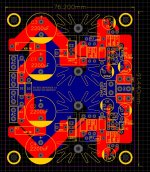
Top side
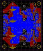
Bottom side
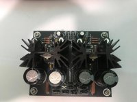
As built and tested.
Attached are the gerber files that can be used to order pcbs from a PCB fab such as www.jlcpcb.com
Attached is a mouser BOM as built. This is for +/-15vdc operation.
I used the Element 14 for certain parts which are cheaper through Element 14. One Rubycon cap was not available from Mouser so an alternative has been suggested.
Attachments
As a reference, to try to settle the dispute, here is a summary of the measured characteristics of the nonoiser (the Dienoiser should be very close):
Output impedance @1kHz: 15µΩ
PSRR @100Hz: 125dB raw (tweakable to 130dB)
Noise density @1kHz: 0.8nV/√Hz (With a ZTX851)
Total noise from 10Hz to 10kHz: 90nV
Output impedance @1kHz: 15µΩ
PSRR @100Hz: 125dB raw (tweakable to 130dB)
Noise density @1kHz: 0.8nV/√Hz (With a ZTX851)
Total noise from 10Hz to 10kHz: 90nV
- Home
- Amplifiers
- Power Supplies
- D-Noizator: a magic active noise canceller to retrofit & upgrade any 317-based VReg