Derivator Dienoiser
What about this?
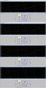
With RC prefilter. R = 1 ohm and C = 4700 uF:

With RCRC prefilter. R = 0,5 ohm and C = 4700 uF:
The 10K trimpot setting allows you to find the most optimal rejection point.
Is it not surprising?
Best regards
Using an opamp in a similar (but not that extreme) role has already been done, by Apex among others, and he probably lifted it from another source.The 10K trimpot setting allows you to find the most optimal rejection point.
Is it not surprising?
Best regards
Without compensations, I predict huge stability problems, and the scheme will only work for PSRR and impedance, not noise: an opamp, even a good one is noisier than a transistor, even a humble BC337
What compensations would you suggest?
I did simulate Diego's regulator, and in fact noise is not as good as a simple Noisator, even using a low noise chip like the LT1115, which is available in LTSpice.
But impedance is the lowest I have ever seen, reaching nOhms on certain frequencies.
I did simulate Diego's regulator, and in fact noise is not as good as a simple Noisator, even using a low noise chip like the LT1115, which is available in LTSpice.
But impedance is the lowest I have ever seen, reaching nOhms on certain frequencies.
You could start with a cap in // with the 560K, and a resistor in series with the input cap.What compensations would you suggest?
Note that even if it looks stable in .tran, that doesn't guarantee the stability of the actual circuit.
It has to be tested for real.
Yes, the gain of an opamp is huge compared to one or two transistors, the question is: will all this gain be usable?But impedance is the lowest I have ever seen, reaching nOhms on certain frequencies.
OK, that matches my measurement on the nonoiser, which is very comparable to the Dienoiser
Practically any medium-power transistor would do better. A cheap and easy upgrade is the BC337, but many are even better: the ZTX851, of course because of its record Rbb value, but many low-noise alternatives exist like 2SC6043 or the good old 2N5401.
Even a cheap Chinese S8050 is significantly better than a BC337.
Note that if you use a very high performance device like the ZTX, the 47 ohm protection resistor will become the main noise source, and should be reduced to 22 or 10 ohm
Hello Elvee,
I have a question about the your denoiser...the old C945 is a good (better) substitute for the BC337? As for the datasheet it is low noise and operating in a linear Hfe range.
No, so-called low-noise transistors of the seventies are in fact inferior to many medium-power devices like the BC337 (or the S8050)
I don't think so, at least for usable devices: you might find that a large power transistor using the same technology as the ZTX like the the 2SC5200 has an even lower Rbb, but using one would not be practical: because of the bulk, the parasitic capacitances, and the behavior at low currents
Is there ANY transistor that is quieter than the ZTX851/951?
Depends on the source impedance. For a 10k source impedance almost any transistor will be queiter!!
For voltage noise its up there with the best, for current noise its not. For best performance at a particular source impedance you want the ratio of voltage noise to current noise to roughly match the impedance so that the combined noise is minimal. A ZTX851 at 10mA is matched to 5 ohms or so.
If you allow yourself to use transformers to transform impedances then the lowest noise device has lowest noise _power_, measured in zeptowatts per √Hz 🙂
So today I replaced R2 with 2 green Leds for about 5.4Vdc output in the Diego D-Noizator.
At last my Cirrus CS4397 Dac has found it's voice.....now I listen to it for hours rather than a few songs.
Thank you Elvee.
Thank you Diego
All else who contributed.
At last my Cirrus CS4397 Dac has found it's voice.....now I listen to it for hours rather than a few songs.
Thank you Elvee.
Thank you Diego
All else who contributed.
Can you please specify which was the exact circuit you used for your supply?
What supply were you using before, and what did change?
What supply were you using before, and what did change?
No, so-called low-noise transistors of the seventies are in fact inferior to many medium-power devices like the BC337 (or the S8050)
Thanks for the information Elvee
So today I replaced R2 with 2 green Leds for about 5.4Vdc output in the Diego D-Noizator.
At last my Cirrus CS4397 Dac has found it's voice.....now I listen to it for hours rather than a few songs.
Thank you Elvee.
Thank you Diego
All else who contributed.
I am very happy to know that now your DAC has found its voice. Enjoy it and thanks for sharing your experience.
The greatest of my respects to you
Good mornin' everyone
carlmart I am using this one. Elvee's sym of diegomj1973 version #404
R2 is 2 green Leds,R3 is 390R.
I was using the LM317 for 5Vdc output....data sheet guidelines.
Oh and the adjustment bypass capacitor is/was 470uf so that's what I use for C3.
carlmart I am using this one. Elvee's sym of diegomj1973 version #404
R2 is 2 green Leds,R3 is 390R.
I was using the LM317 for 5Vdc output....data sheet guidelines.
Oh and the adjustment bypass capacitor is/was 470uf so that's what I use for C3.
Attachments
Note that using a non-linear component as R2 will seriously blunt the performance of the Die- or Denoiser: it will shunt its output with a low dynamic impedance of forward-biased diodes.
Time to remind that the denoiser (and the Dienoiser) should only be applied to plain-vanilla regulators (as per datasheet examples)
Time to remind that the denoiser (and the Dienoiser) should only be applied to plain-vanilla regulators (as per datasheet examples)
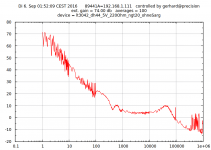
This measurement shows the noise profile of the denoizer against a state of the art linear regulator, the LT3042.
View attachment 806870
I decided that measurements against a bare LM317 were useless, so I mounted an LT3042 next to the 1000x head amp and made it switcheable.
The 50Hz and its harmonics are because of insufficient shielding of the denoizer. It is not because of lacking PSRR as the following measurements will show.
I definitely doubt the LT3042 measurements, starting with the missing absolute scale.
My measurements look this way:
(ed. that does not seem to load in finite time)
Circuit is from the data sheet and results are like the data sheet. (red trace)
The strong rise at low frequencies goes on the undersized input capacitor
of the preamplifier. That has been changed in the meantime.
Increasing the output cap of the 3042 beyond the recomendend value creates
a noise peak. (green line). If you insist in a larger cap, you need some damping R.
The other picture is the LT3042 with an external DH44 BJT for large output current.
Also 1:1 from the data sheet.
< spectrum_lt3042_DH44 | Noise spectrum of the LT3042+ D44VH10… | Flickr >
The other pics to the left/right show the noise of some Zeners, LEDs and other references.
All plots are scaled that 0 dB is 1nV/rtHz, which is abt. the equiv. input noise density of an AD797 or LT1028.
Gerhard
Attachments

Last edited:
PL802,
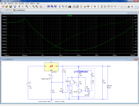
I took the liberty to simulate your regulator. First two use the green LED you tried, though only one in my case to get the output you need. Your LED must be different.
Then I replaced the LED with a 680 ohm resistor, also to get to the voltage you need.
In this case the comparison was between PSRR, and the curves speak by themselves. Elvee seems to be right about the LED worsening the results, and impedance or noise should be worst than using a simple resistor. Why don't you try that option, instead of the LED?
Also have a look at the improvement you should have by just adding a 1 ohm resistor before your input filter cap, as suggested by Diego. On both versions.
Attachments
> Your LED must be different.
For starters, in the direction. LEDs are no Zeners.
As drawn, the ADJ pin floats somewhere near the output without
any connectivity to GND. The LED carries just some nA of backward
current.
If you turn the LED around, you may be able to set the output voltage
but most of the amplified noise voltage is shorted to GND through the
diode's small differential resistance. So, almost no correction.
Sorry, I don't get it.
You say the direction I placed the LED is incorrect?
I could set the output voltage the way I used it.
You say the direction I placed the LED is incorrect?
I could set the output voltage the way I used it.
- Home
- Amplifiers
- Power Supplies
- D-Noizator: a magic active noise canceller to retrofit & upgrade any 317-based VReg