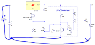
This very interesting thread has had many out of topic sequels.
I think all has been said already on denoising a LM317 based regulator.
I am very found of the 1 transistor denoiser, an easy friendly dependable circuit whose purpose goes way beyond LM317 based regulators.
I think all has been said already on denoising a LM317 based regulator.
I am very found of the 1 transistor denoiser, an easy friendly dependable circuit whose purpose goes way beyond LM317 based regulators.
Let me understand. So you the Denoiser version designed by Diego that had two transistors, and changed to the Denoiser designed by Elvee that has just one transistor, and the oscillation ended?Changed it to a denoiser and its now rock solid. It takes around 8 seconds to get to stable voltage of 12.81 under load. The transistor is directly jumpered to R16s closest pad. The dnoiser is better than running the regulator without one.View attachment 1348261
Which grounding approach is most appropriate for PCB? Full ground plane?
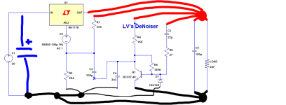
Is separating the regulator circuit from the "high" current output more appropriate? (image attached)
*Same question for the positive track, is taking the reference of everything from the output capacitor the most appropriate?
Is separating the regulator circuit from the "high" current output more appropriate? (image attached)
*Same question for the positive track, is taking the reference of everything from the output capacitor the most appropriate?
Attachments
No ground plane.
You must be in control of current paths.
Figure high current loops.
Make the loop area, small.
You must be in control of current paths.
Figure high current loops.
Make the loop area, small.
Your positive version is ~OK, but the emitter of the transistor should go directly to the output GND
None of them can be applied if the Denoizator module is applied, as it originally was suggested, to already existing 3X7 regulators. Only the terminals of the Denoizator parts can be re-directed.
Is this a complete power supply that has the denoizer circuit incorporated into it?
Can this be modified to provide +50vdc and -50vdc?
Thank you for the clarification
Is this correct? My intention is to separate the "high" current and the control signal.Your positive version is ~OK, but the emitter of the transistor should go directly to the output GND
Attachments
Don't overthink the layout more than necessary.
Start from here:

and connect the two small arrows of the denoiser directly to the load.
There is no need for further complications. Preferably use 10nF for C2, to be on the safe side
Start from here:
and connect the two small arrows of the denoiser directly to the load.
There is no need for further complications. Preferably use 10nF for C2, to be on the safe side
The LM317HV is limited to 60V, which is too close to 50V for comfort, and AFAIK, there is no 337HV.Is this a complete power supply that has the denoizer circuit incorporated into it?
Can this be modified to provide +50vdc and -50vdc?
Thank you for the clarification
Yes, people will tell you that the regulator only sees the difference between in and out, but that's the theory. In practice, things always end with molten silicon
The LM317HV is limited to 60V, which is too close to 50V for comfort, and AFAIK, there is no 337HV.
Yes, people will tell you that the regulator only sees the difference between in and out, but that's the theory. In practice, things always end with molten silicon
You could replace C709/10 with a denoiser: it should work and result in a super-quiet regulator (untested though)
Maybe someone could draft thatYou could replace C709/10 with a denoiser: it should work and result in a super-quiet regulator (untested though)
Does top of R4 need to be connected close to load? That only supplies power to denoiser. I only run positive side of C1 as sense on output of PCB. And emitter of Q1 to ground output of PCB.Don't overthink the layout more than necessary.
Start from here:
View attachment 1358819
and connect the two small arrows of the denoiser directly to the load.
There is no need for further complications. Preferably use 10nF for C2, to be on the safe side
No, certainly not but keeping the denoiser function together helps avoiding silly mistakesDoes top of R4 need to be connected close to load?
- Home
- Amplifiers
- Power Supplies
- D-Noizator: a magic active noise canceller to retrofit & upgrade any 317-based VReg


