Hi jplch
Did you check the information about changing DIP oscillators to D-Clock?
It's found here: http://www.newclassd.com/index.php?page=20
Another thing is, when you change the clock in a separate DAC, you may have to syncronize the transport to the new clock. This is the case if the DAC does not have it's own resampler.
Dear Lars, thank you for your quick reply. I'll follow your suggestion with the diode and the resistor. The strange thing is that the dac (when set to 5V) was locking to the transport, this is why I did not bother trying the diode trick, since in the d-clock pages you refered to, it was suggested in the case when locking was problematic; also I guess synchronizing the transport (Mark Levinson No37) to the dac is not needed, since it locks properly, right ?
Yes, but the reason why it is not necessary to sync them is, that your DAC has a resample circuit on borad (The CS8420).
Good luck
Good luck
Dear Lars, yes I noticed the resampling crystal chip. Well, no luck. The diode trick, with and without the 100k resistor, did not change anything. Could it be that I am providing the supply voltage from a wrong location ? I picked +15V up not from a capacitor location, but already after a voltage regulation, "closer" to the digital circuit. Could it be that the clock is somehow polluting the rest of the digital circuits ? I guess not to the point of cancelling the conversion, but I prefer to ask, since I do not see what else could be wrong. Maybe another point : the original clock was 50Mhz, and I am trying to replace it with your 45.1584Mhz. This should be ok, since Guido Tent, using his clock at 45.1584, claims it worked perfectly, and before writing to you, i checked with him to get the confirmation.
And lastly, on my specimen of your clock, there is no solder closing the circuit at the location B2, whereas on the illustration of the clock on your web page there is. How about that ? Is it material here ? How about the other one, marked B1 ?
I am ready to experiment various suggestions, just provide me some, since myself I exhausted mine...best, Jan.
Is the blue LED lighting? (indication of proper power).
The D-Clock can not pollute the power rails, so that's not an option.
B1 and B2 are for frequency adjustment, and so may change from one clock to another. No reason to worry about those.
You may want to look at proper setting of B3 (5V)
and B4 (Ignore should be always on.)
The D-Clock can not pollute the power rails, so that's not an option.
B1 and B2 are for frequency adjustment, and so may change from one clock to another. No reason to worry about those.
You may want to look at proper setting of B3 (5V)
and B4 (Ignore should be always on.)
Actually, there is some progress here (Yes, 5V, "ignore", etc were all ok...). I could get suddenly some decent sound while giving it another try, but then, when I decided to put back the dac cover, gone it was...and I could not make it back, moving wires, resoldering, etc. At this point, it looks like I have some problem of proper contact (soldering?), ground or else ... I'll try to work it before bothering you again. Just in case voltages at the HC entry points are around 750 mV. Thanks for your help, jplch.
Dear Lars, well, I could not reproduce the working situation reported in my last post. I have tried really EVERYTHING soldering, resoldering, and really need some new input now. For instance, is it possible to increase the output of your clock ? Compared to the standard Dip 8 oscillator, it outputs, when substituted, 800mV pp instead of 1.2 V pp and since I have tried everything without succes, maybe this is the reason of my problems, like it being not strong enough to drive the two 74HC's ? Also, I asked you already if the length of the coaxial cable is of some importance : could it be that shortening it substantially would improve things ? I prefer to ask before cutting it 🙂 Best, jplch.
Hello again
There is no reason to shorten it, the length has no bearing.
The voltages you are measuring are completely off. Both for the DIP and the D-Clock. They should be more like 5Vpp.
Are you using the 5V setting on the D-Clock?
Best regards
There is no reason to shorten it, the length has no bearing.
The voltages you are measuring are completely off. Both for the DIP and the D-Clock. They should be more like 5Vpp.
Are you using the 5V setting on the D-Clock?
Best regards
Dear Lars, well I too was suprised by these low voltages. I am measuring the output voltage between the ground (the ground of the board where the dac circuit is, which is decoupled from the mains ground by small caps - the same is true of the supply board) and the output pin of the DIP8, when inserted into the circuit, I mean when driving the Hcs (which, by the way, makes the dac work perfectly). Same for the clock (yes, 5V is set on), i.e. voltage between the two conductors of the cable, when inserted into the circuit. Assuming that my reading is false (though I see no reason why...), the clock output would then turn out to be ok too, but then I do not see what causes the malfunction when simply substituting the signal of the Dip8 with the clock one...
best, Jplch
best, Jplch
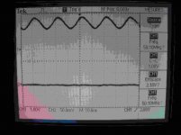
Dear Lars, here are the scope shots (jpeg) : the first one (i1) shows the d-clock output, measured across the central conductor and the braid of the coaxial. The other one (i2) shows the output of the dip8 stock clock as taken between the output pin, and the ground one.
Attachments
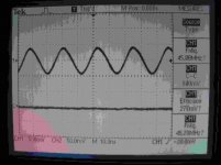
I was imprecise above : in the case of the dip8, it is inserted in the dac circuit, with the ground pin attached to the digital ground, which is decoupled from the mains ground by a small capacitor. In the case of the d-clock, it is not inserted in the dac circuit. This I guess explains the dc offset.
Dear Lars, a long time has passed since my last post with the shots of the scope...any reaction ?
Sorry i didn't see your post until now.
Is that a TDS 210? It seems the bandwidth is limited.
Anyway it looks like you have zero DC component on your clock signal, which is why the HC chips are not picking up. It looks like you are running in 3V mode, the signal level is very low.
To get a DC component suitable for your circuit i suggest connecting a 100k from clock signal to GND and a 100k from clock signal to +5V on the 74HC08 that is receiving the clock signal. (Pin 14). That will give you a proper DC level.
About the signal level, which is way too low, i'm no sure if itøs a bandwidth limit of the scope, or you are using a 1:1 probe maybe?
If you want to make sure to get a fast response, you are also welcome to contact me directly by mail on: lc@dexa.dk.
It's LC in the beginning (my initials). ;-)
It's LC in the beginning (my initials). ;-)
Dear Lars, thanks for the response ! Yes it is a TDS 210, but it is supposed to go up until 60MHz, or so I thought...
Concernign the probe, it is indeed set on 1:1 : however, being suspicious, I checked it with a battery continuous voltage and got a correct reading. Could it be that it is different for a Mhz signal ?
Again, the 5V is set on the dexa-clock, solder correctly applied.
Now, I have not yet tried your suggestion (was heavily overloaded with work) but I shall do so this week-end and let you know writing on your e-mail address. Thanks again for your help !
Hi again, I was puzled with your remarks concerning the probe. Some similar ones are, in 1:1 position, indeed bandwidth limited, so maybe this the reason of my measuring a low signal of the clock. I still have to try your suggestion. Write to you soon.
Is it possible for D-Clock to re-clock the SPDIF output of the player? I have a theta miles and I'd like to reclock the SPDIF output, as I use it exclusively as a transport with external DAC (bel canto DAC3).
Thank you
Thank you
- Status
- Not open for further replies.
- Home
- Source & Line
- Digital Source
- D-Clock it.....................