Yamaha NS-1000 on thevintageknob.org
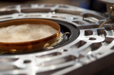
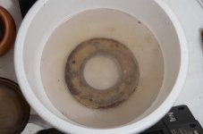
Is that gray area between the pole piece and the magnet well below the gap but not at the base of the pole piece a shorting ring? Unusual location.
Is that gray area between the pole piece and the magnet well below the gap but not at the base of the pole piece a shorting ring? Unusual location.
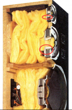
Looks like foam or felt damping material in the circled areas of the mid and tweeter.Is that gray area between the pole piece and the magnet well below the gap but not at the base of the pole piece a shorting ring?
The mid-range back chamber is full of fiberglass damping too, with another bit of black material in the dome center- must have a screen behind the dome to keep that stuff in place.
Attachments
+1
The cavity behind the gap, combined with the gap itself and the VC, could tune to a nice resonance in the driver’s working range. The damping should take care of that. Nice magnet assembly design for the 70s though, as we know from Yamaha then.
The cavity behind the gap, combined with the gap itself and the VC, could tune to a nice resonance in the driver’s working range. The damping should take care of that. Nice magnet assembly design for the 70s though, as we know from Yamaha then.
Too far from the gap to make any effect so like others I suspect foam or felt or similar.
To add a proper one (imagine speaker pointing up) they should turn (on a lathe) a tringular section aluminum "washer" filling the missing steel under the top plate , the empty area which now appears black on the picture, or one sitting on top of the hollow/vented polepiece.
Very little space available between dome and polepiece.
The mid- and high dome drivers are practically always underhung constructions and do not profit from shorting ring because underhung construction voice coils are always in the most constant magnetic field within the air gap. Huge mid domes could theoretically profit from it (copper pole piece cap i.e.) but they are already very well above of their usable frequency range where the rising inductance/impedance doesn't affect the sound reproduction anymore.
Like some already mentioned it, that ring is a foam piece which dampens the resonance of the chamber below the voice coil/air gap. And if you are looking to buying a Yamaha NS speaker, these are excellent, even compared with modern speakers. These foam rings can be a problem though, the foam is now 40+ years old and it very likely decomposed meanwhile. The influence on the sound is minimal but it can be problematic if the remnants of the foam find their way into the air gap. Disassembling them is really not a deed you want to do, you can't replace the foam from the front, you'd need to disassemble the driver completely, even the magnet and pole plate and -piece. So if you are buying the NS-1000 (or smaller models) and got problems with the foam (it shows in the impedance and distortion measurements), just get the diaphragm out, clean the air gap and re-assemble them.
just
It is indeed a foam ring to dampen cavity resonance, as others have already said. It is mostly sealed from the environment, so foam decomposition is not in issue. At least in my drivers the polyurethane was ~like new.
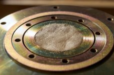
The real problem with Yamaha drivers from the 70s is corrosion. Either the glue that holds magnetic circuit is corrosive itself, or the salty ocean air and moisture gets in through the micropores in adhesive layer, weakening the seam. In static condition this is of no concern, but in transit magnet dislodges, clincing the voice coil, requiring meticulous work to take the driver apart without damaging the VC.
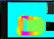
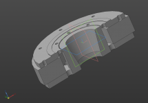
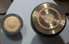
On the bright side it allowed me to take measurements of magnet, flanges and pole piece. I made a 3D model of the circuit and simulated in in FEMM, verifying great linearity of the design.
The real problem with Yamaha drivers from the 70s is corrosion. Either the glue that holds magnetic circuit is corrosive itself, or the salty ocean air and moisture gets in through the micropores in adhesive layer, weakening the seam. In static condition this is of no concern, but in transit magnet dislodges, clincing the voice coil, requiring meticulous work to take the driver apart without damaging the VC.
On the bright side it allowed me to take measurements of magnet, flanges and pole piece. I made a 3D model of the circuit and simulated in in FEMM, verifying great linearity of the design.
Attachments

It is indeed a foam ring to dampen cavity resonance, as others have already said. It is mostly sealed from the environment, so foam decomposition is not in issue. At least in my drivers the polyurethane was ~like new.
The chamber below the VC isn't airtight, so the ambient/enviroment does affect it too. But the aging by gasses/the atmosphere isn't critical, that's true. The main part of the aging comes from the temperature of the driver itself. The driver is damped and on the back is the glass wool, so the heat dissipation isn't as good as in other speakers. The front plate still dissipates heat, so in general, heat isn't dangerous for the VC but it still contributes to the aging of the foam. And if the foam looks like new it doesn't necessarily mean it isn't starting to decompose. The break up of long molecule chains can't be seen and isn't critical for its function in the driver since it's not in any mechanical stress. And again, your testemony shows it's likely not a major concern.
The real problem with Yamaha drivers from the 70s is corrosion. Either the glue that holds magnetic circuit is corrosive itself, or the salty ocean air and moisture gets in through the micropores in adhesive layer, weakening the seam. In static condition this is of no concern, but in transit magnet dislodges, clincing the voice coil, requiring meticulous work to take the driver apart without damaging the VC.
The salty ocean air is indeed a problem, there are Seas drivers (aluminium/magnesium cone) which, in fact, actually corrode because of the salt in the air. I faintly remember a thread here in the forum about that.
The glue got only a very thin surface and isn't very susceptible towards salt. However, to produce the polyurethane foam, isocyanate is used and while the production of the driver not everything of it is gone. And that's the problem, because it gassed out within the driver, and you probably already guessed it, it's aggressive towards the glue. No, it doesn't still gass it out but it weakened the glue so it wasn't a such strong connection like it was calculated and intended. It's not the main problem but it contributed to it.
On the bright side it allowed me to take measurements of magnet, flanges and pole piece. I made a 3D model of the circuit and simulated in in FEMM, verifying great linearity of the design.
You've done an excellent job there, and it will greatly help to maintain these awesome speakers (which outlasted much, much newer speakers already). Any information is very valuable because the documentations on the drivers (or even on the whole speaker) is very rare and often hard to find, if there's anyting at all. So thank you very much!
Better late than never, I guess 🙂
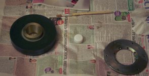
I simply screwed in 6 M4 screws until they touched the magnet and evenly tightened them until the top plate was lifted. You can add some acetone or xylol at the rim and into the holes if some patches of glue still hold adhesion.
I poked the foam damper a bit. It's clean and springy, not mushy or dry. No off-whiteness of deterioration either.
Attaching some more photos and B(x) graph for the midrange driver.
Hello VoxCelestial,
How exactly have you managed to disassemble the magnet and the topplate?
I simply screwed in 6 M4 screws until they touched the magnet and evenly tightened them until the top plate was lifted. You can add some acetone or xylol at the rim and into the holes if some patches of glue still hold adhesion.
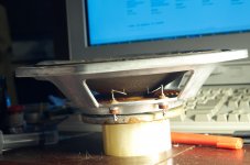
A minor nitpick: it is airtight after all. Certainly not helium-proof, but definitely not allowing for substantial gas transfer. It is sealed from behind by a steel cap sitting on foam gasket, and from the front by the membrane assembly itself, as seen onte the second image in my previous post.The chamber below the VC isn't airtight, so the ambient/enviroment does affect it too. But the aging by gasses/the atmosphere isn't critical, that's true. [...]And if the foam looks like new it doesn't necessarily mean it isn't starting to decompose. The break up of long molecule chains can't be seen and isn't critical for its function in the driver since it's not in any mechanical stress.
I poked the foam damper a bit. It's clean and springy, not mushy or dry. No off-whiteness of deterioration either.
This may've contribute to the mid failure, yes, but no PU foam was affecting woofer magnet, just corrosion. It was rather severe, so I had to chemically clean and phosphate coat the top plate.THowever, to produce the polyurethane foam, isocyanate is used and while the production of the driver not everything of it is gone. And that's the problem, because it gassed out within the driver, and you probably already guessed it, it's aggressive towards the glue. No, it doesn't still gass it out but it weakened the glue so it wasn't a such strong connection like it was calculated and intended. It's not the main problem but it contributed to it.
Thanks! It's been a pleasure working with them (and listening afterwards).You've done an excellent job there, and it will greatly help to maintain these awesome speakers (which outlasted much, much newer speakers already).
Attaching some more photos and B(x) graph for the midrange driver.
Attachments

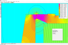
Next question: how did you produce the BL graph? Looks almost too good (lin.&symm.) to be true....I suppose it is a sim based on FEMM and not a real measured curve?
VoxCelestial -- please explain in more detail! I got a pair of those JA801 tweeters a couple years ago, still considering just how to use them.I simply screwed in 6 M4 screws until they touched the magnet and evenly tightened them until the top plate was lifted.
Also, in an earlier pic, you seem to be using a toothbrush to scrub at the dome with detergent?!! That is safe? for the beryllium dome as well as for you? It suggests you had the dome + VC apart from the rest of the driver? Please explain.
And have you done any other measurements such as FR, phase, distortion, off axis responses, etc?
Measured a number of the mids over the years and they exhibited the lowest harmonic distortion I’ve seen. The tweeters varied more than the mids, and I think that has to do with consistency in the application of the viscoelastic coating to the fiber suspension; L to R matching of all drivers in speaker pair, 1dB; cross-batch difference of the mids from 1975-1996, 0.5dB at 500Hz and 1.5dB at 6-8kHz; cross-batch difference in tweeter sensitivity, a larger 4dB.
For the JA-801, 0.04-0.07% (<-70dB) harmonic distortion above 500Hz at 90dB, with two closely spaced peaks at Fs. No peaks were detected above Fs. My measurements were semi-anechoic, so there was still some energy reflecting and raising the noise floor. The response is uneven above 8kHz, but extends to over 22kHz on-axis. Off axis response was wide to 6kHz even at 45 degrees. There are modes at 4kHz, 8kHz, and 16kHz in the frequency versus time domain that are mostly negligible with the crossover installed.
I can post some graphs when I’m at my station, but VoxCelestial will probably get to it before then.
Last edited:
kouiky -- thanks for that! 🙂 I've done some basic measurements on mine and can concur with most of your findings... tho I don't recall such low HD.
Still awaiting VoxCelestial's reply.
IIRC, the moving mass of the 1" beryllium dome was spec'd as 0.03 gram, which always seemed too low to be believable, but it begs the question of what is the mass of the big dome. Bliesma cites its 34mm Be dome as 0.26 grams; perhaps this Yammy could be 0.75g?
Still awaiting VoxCelestial's reply.
IIRC, the moving mass of the 1" beryllium dome was spec'd as 0.03 gram, which always seemed too low to be believable, but it begs the question of what is the mass of the big dome. Bliesma cites its 34mm Be dome as 0.26 grams; perhaps this Yammy could be 0.75g?
When I measured the NS-1000Ms, the impedance, response and distortion were exactly like in the Yamaha brochures, even after 40 years, with the exception that no peak was observed in HD in the midrange. With the crossover removed for testing, the tweeters distortion above 1.5kHz was, at its worst, -52dB and at its best -64dB.
The Yamaha beryllium tweeter domes are only 30 microns thickness.
The Yamaha beryllium tweeter domes are only 30 microns thickness.
Last edited:
- Home
- Loudspeakers
- Multi-Way
- cutaway of 70s Yamaha middome - is this a shorting ring?