Typical center channel speakers have never really worked for me. Typical flat screen TVs force you to place the speaker above or below and then you try to angle the CC speaker so you are not always listening off axis. Then there are BR ports that exit the backside making it hard to place them in a TV stand or against a wall. A lot of them (my Paradigm CC370-v4 included) are 2way MTM designs that create off axis horizontal lobes because they XO to the tweeter at high freq.
I'd like to design a CC that is better suited to how I will use it and still work with the rest of my HT system. The room is being renovated, and the CC has to suite the new location (a fireplace column) as best as it can.
The fireplace column will hold a direct vent gas fireplace (Valor Linear + Heatshift kit convection cooling), a 48"x36"x8" pocket for a VESA mounted 50" TV and a center channel speaker. The pocket includes ~5" air space behind the TV (when flush) for convection cooling.
Versions :
V1 : 2x DC130B-4 + CX120-8 Coax : V1 : 2x DC130B-4 + CX120-8 Coax
V2 : 2x DC130B-4, PT6816 Planar : V2 : 2x DC130B-4 + PT6816 Planar
V3 : 4x Dayton PC105-8 : V3 : 4xPC105-8
V4 : 4x DC130b-4, PT6816 Planar : V4 : 4xDC130B-4 + PT6816 Planar
V5 : 4x DC130B-4 + 3FE25-8 + TD20F : V5 : 2xDC130B-4 + 3FE25-8 + TD20F
.
Last edited:
Often wondered if the center channel really needs to produce bass and to a limited degree high frequencies. Might a full range driver, limited to mid range frequencies, be a good choice? This might, as well, make placement much simpler.
V1 dual DC130B-4 with CX120-8 Coax
First attempt.
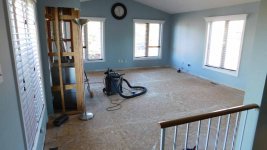
Pic#1 : shows the wood fireplace (now removed) and the room.
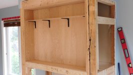
Pic#2 : shows the column reframed for the new gas fireplace and TV pocket.
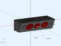
The sitting area is about -30deg and >=2m out from the CC shelf. V1 is a 3 way design using dual DC130b-4 woofers and a CX120-8 coax. If the woofers are close enough and XO'd low enough it should reduce the lobbing. The Midrange and Tweeter are coax so that should minimize lobbing at the MF-HF XO. The woofer design is BR like the rest of the HT system, only the BR ports are now out the front. The baffle is angled down -30deg to the sitting area.
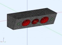
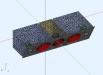
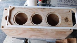
Pic#3 : the proposed shape and organization
Pic#4 : the interior design, 3 chambers, and port locations
First attempt.
Pic#1 : shows the wood fireplace (now removed) and the room.
Pic#2 : shows the column reframed for the new gas fireplace and TV pocket.
The sitting area is about -30deg and >=2m out from the CC shelf. V1 is a 3 way design using dual DC130b-4 woofers and a CX120-8 coax. If the woofers are close enough and XO'd low enough it should reduce the lobbing. The Midrange and Tweeter are coax so that should minimize lobbing at the MF-HF XO. The woofer design is BR like the rest of the HT system, only the BR ports are now out the front. The baffle is angled down -30deg to the sitting area.
Pic#3 : the proposed shape and organization
Pic#4 : the interior design, 3 chambers, and port locations
Attachments
Often wondered if the center channel really needs to produce bass and to a limited degree high frequencies. Might a full range driver, limited to mid range frequencies, be a good choice? This might, as well, make placement much simpler.
It would, and I did think about a simple full range design. I keep reading about how much content is delivered in the CC for TV programming so as a start the V1 might be more complex than needed but I wanted at least 90deg horizontal coverage over most of the spectrum. It would be interesting to compare them to see how much I'm really gaining.
A decent compromise would be a box, with three appropriate full ranges.
The center speaker facing straight out, with the other two speakers angled outwards at about 30 degrees.
This would "spread" the horizontal output, covering the listening area.
If it's imperative to angle them downwards, the box can be tilted, or designed with a tilted front.
The center speaker facing straight out, with the other two speakers angled outwards at about 30 degrees.
This would "spread" the horizontal output, covering the listening area.
If it's imperative to angle them downwards, the box can be tilted, or designed with a tilted front.
V1 BR and XO design
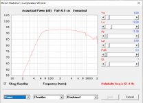
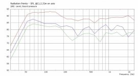
Using HornResp the BR design requires 6-8L and ports tubes ID=1.5" x 3". Pic#1 has the power curve and combined LF rolloff. The LF rollof is comparable to the CC370-v4 low end.
Using Xsim for the XO design. The CX130-8 FR a little bumpier than I would like. There is one MF dip as well as an HF dip+bump that I will just live with for now to preserve sensitivity. Overlapping the MF+HF a little helps flatten the curve. The LF-MF XO is 2nd order @800Hz , and MF-HF is 3rd order @5.8Khz. This is different than the 2 way CC370 (3rd order @ 2Khz) . The min impedance is ~6 ohm and similar to my other Paradigm speakers so my Yamaha receiver should like it. The speaker sensitivity is also ~90dB/W which is also similar to the other Paradigm speakers.
Attachments
A decent compromise would be a box, with three appropriate full ranges.
The center speaker facing straight out, with the other two speakers angled outwards at about 30 degrees.
This would "spread" the horizontal output, covering the listening area.
If it's imperative to angle them downwards, the box can be tilted, or designed with a tilted front.
V1 has -30deg baffle so I agree with that.
Usually arranging a horizontal array (all same driver in line) will increase beaming at higher freq. Changing the angles risks lobes and interference as the driver coverage narrows with freq.
Are you implying all drivers, are always on? Or some type of beam steering at higher freq?
Inductors
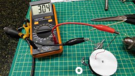
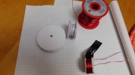
Everytime I need an inductor the shipping cost's more than the part and then there's the delay. So I bought a spool of magnetic wire and tried out winding my own. This is very convenient for prototypes as it only takes a few minutes and I can easily adjust them. I even recover the wire when I'm done. Maybe I'll start collecting discarded electric motors 🙂
Pic#1 : shows the design for a 3mH inductor using Wheeler's formula. A simple spreadsheet can be used to optimize the coil ID, OD, length. Normally I would want thicker wire (lower resistance) and an iron core for something this large and intended for a low XO. However this is quicker for prototypes.
Pic#2,3,4 : Foam board can be used to make a quick spool, once you have the ID, OD, L of the coil. Wheeler's formula is very accurate. I filled the spool and adjusted +/- a few turns to get the precision I wanted. The metal bolt I used with a drill to wind the coil needs to be removed for measurement. A few zip ties hold it all in place.
.
Attachments


V1 polars
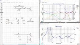
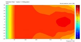
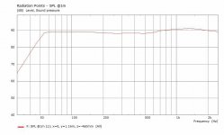
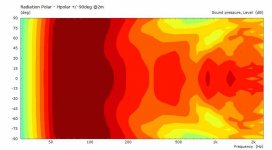
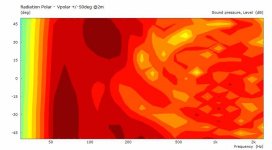
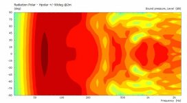
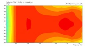
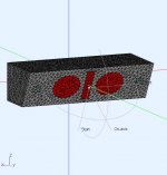
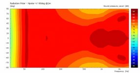
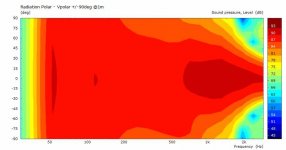
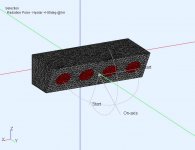
This is the AKABAK sim results for the V1 in 4Pi space. This is a starting point to see how much interference there is between the 2 woofers.
The model includes the LEM electrical models for the driver motors and the XO (800Hz, 5.8KHz) and BEM acoustic models for the chambers,ports and drivers.
You can see the off axis horizontal polar narrowing and the asymmetric vertical polar (30deg @top edge, 150deg @bottom edge). Still, there is at least 90deg horizontal coverage at the narrowing. I would like to improve this, but I need to check what happens when this design is mounted in the fireplace column.
.
Attachments

Effect of the FP column
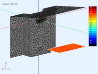
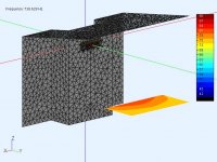
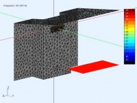
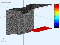
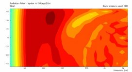
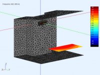
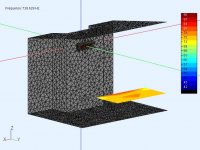
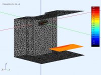
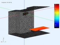
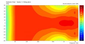
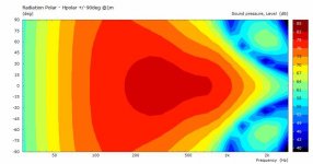
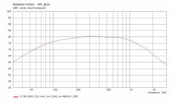
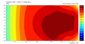
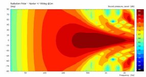
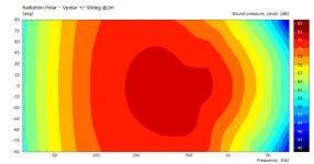
These are some results from AKABAK BEM sim to see what effect the fireplace column will have on the polars. I have left out the floor in this sim so there is no ground bounce (yet). The sloped cathedral ceiling is causing a vertical bounce shown in the vertical polar. I've limited the Vpolar to +/-45 deg.
The column forms a wider baffle and helps boost the LF when compared to the 4pi simulation (as expected). The Hpolar dip is still there but it also has diffraction from the column edges (also expected). It looks like I put a small speaker on a wide baffled cabinet and pushed it against the wall. It behaves like that as well. 🙂
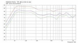
The observation field (1mx2m floating rectangle) represents SPL at ear level when sitting on a couch. It's not too bad but there is attenuation at the Hpolar dip and the system could use some EQ to flatten the response.
.
These are some results from AKABAK BEM sim to see what effect the fireplace column will have on the polars. I have left out the floor in this sim so there is no ground bounce (yet). The sloped cathedral ceiling is causing a vertical bounce shown in the vertical polar. I've limited the Vpolar to +/-45 deg.
The column forms a wider baffle and helps boost the LF when compared to the 4pi simulation (as expected). The Hpolar dip is still there but it also has diffraction from the column edges (also expected). It looks like I put a small speaker on a wide baffled cabinet and pushed it against the wall. It behaves like that as well. 🙂
The observation field (1mx2m floating rectangle) represents SPL at ear level when sitting on a couch. It's not too bad but there is attenuation at the Hpolar dip and the system could use some EQ to flatten the response.
.
Attachments
-
 V1-FP-ObsField-EarLevel@2kHZ.jpg66.2 KB · Views: 57
 -
 V1-FP-ObsField-EarLevel@902HZ.jpg66.1 KB · Views: 62
 -
 V1-FP-ObsField-EarLevel@738HZ.jpg66 KB · Views: 68
 -
 V1-FP-ObsField-EarLevel@494HZ.jpg65.9 KB · Views: 58
 -
 V1-FP-ObsField-EarLevel@181HZ.jpg66.1 KB · Views: 56
 -
 V1-FP-ObsField-EarLevel@66HZ.jpg66.3 KB · Views: 61
 -
 V1-FP-Vpolar-2m.jpg23.5 KB · Views: 60
 -
 V1-FP-Hpolar-2m.jpg25.1 KB · Views: 58
 -
 V1-SPL-on-axis-1m-2m-3m.jpg39 KB · Views: 60
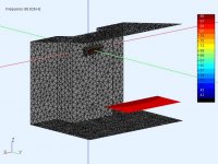
Effect of the column + floor
.. and with the floor. All the surfaces are modeled as ideal reflectors. The actual floor reflections should be attenuated by furniture and possible area rug.
.
.. and with the floor. All the surfaces are modeled as ideal reflectors. The actual floor reflections should be attenuated by furniture and possible area rug.
.
Attachments
-
 V1-FPF-ObsField-EarLevel@2KHz.jpg66.6 KB · Views: 62
 -
 V1-FPF-ObsField-EarLevel@902Hz.jpg66.6 KB · Views: 75
 -
 V1-FPF-ObsField-EarLevel@738Hz.jpg66.4 KB · Views: 56
 -
 V1-FPF-ObsField-EarLevel@494Hz.jpg66.3 KB · Views: 63
 -
 V1-FPF-ObsField-EarLevel@181Hz.jpg66.4 KB · Views: 109
 -
 V1-FPF-ObsField-EarLevel@66Hz.jpg66.5 KB · Views: 110
 -
 V1-FPF-Vpolar-2m.jpg26.6 KB · Views: 108
 -
 V1-FPF-Hpolar-2m.jpg27.8 KB · Views: 113
 -
 V1-FPF-On-Axis-SPL-2m.jpg38.1 KB · Views: 107
V1 build
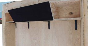
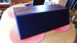
V1 will be a starting point for listening and measuring. These are a few pic of the construction.
The plywood was stained with some left over walnut stain. It looks ugly on plywood, and would be better had I painted it black or even clear. This plywood was left over from stiffening the subfloor preparing for hardwood flooring.
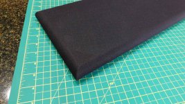
The removable grill, mounting pins and material are new to me. Fairly easy to work with and I was concerned about the material corner appearance, and pin alignment. The frame is 11/16" quarter round which is easy to work with but not good w.r.t diffraction. The next removable grill will be more acoustically integrated.
Did a quick power up and listen with it sitting on a stand. Sounds good, but I still need measurements on a stand and in the fireplace column.
.
V1 will be a starting point for listening and measuring. These are a few pic of the construction.
The plywood was stained with some left over walnut stain. It looks ugly on plywood, and would be better had I painted it black or even clear. This plywood was left over from stiffening the subfloor preparing for hardwood flooring.
The removable grill, mounting pins and material are new to me. Fairly easy to work with and I was concerned about the material corner appearance, and pin alignment. The frame is 11/16" quarter round which is easy to work with but not good w.r.t diffraction. The next removable grill will be more acoustically integrated.
Did a quick power up and listen with it sitting on a stand. Sounds good, but I still need measurements on a stand and in the fireplace column.
.
Attachments


My mum used to say she'd put my speakers in the fireplace, but I don't think this is entirely what she meant?
 , many ways to interpret that,... mine is the "non combustible" way
 V1 - LF narrowing and the XO point
The V1 has the woofers as close as practical to the midrange (15cm C-C woofer to midrange coax).
Using my initial XO=800Hz gives me the min horizontal width I think I want, but it could be made wider. Moving the XO point lower means more midrange cone movement that I'd like to avoid because it's also acting as the tweeter's horn.
Using the V1 model to see the effect of moving the LF-MF XO point lower. A common RoT is to use lambda/4 spacing at the XO point, which is 573Hz for V1 spacing.
Pic [1,2,3] -> [800Hz, 530Hz, 400Hz]
.
Attachments

V2 - Dual woofer + Planar tweeter
A slim planar tweeter (like a PT6816) would allow the woofers to move closer together to reduce the horizontal narrowing effect (XO=800Hz). It can also reduce the MF-HF vertical beamwidth to reduce ceiling reflections.
The driver radiation surfaces have been simplified. The sim was 4pi space.
.
A slim planar tweeter (like a PT6816) would allow the woofers to move closer together to reduce the horizontal narrowing effect (XO=800Hz). It can also reduce the MF-HF vertical beamwidth to reduce ceiling reflections.
The driver radiation surfaces have been simplified. The sim was 4pi space.
.
Attachments
Last edited:
You could also use an AMT in the middle with a short horn like 18sound XMT200 which provides excellent horizontal coverage sown to 600Hz.
Nice project! For a cinema system the goals are quite different than for HiFi. You need to have good horizontal coverage over a wider range.
Nice project! For a cinema system the goals are quite different than for HiFi. You need to have good horizontal coverage over a wider range.
Thanks.
I like the idea of using a short horn to control the pattern, but it would also require moving the woofers further apart and moving the XO lower, putting more demand on the planar.
I think I need some ideas to compensate for the LF cancellation dip when the woofers are spaced more than ~lambda/4 apart at XO.
V3 - Quad Full range PC105-8
This is an attempt to shape the horizontal polar using a mini array of full range drivers (PC105-8). The sims are in 4pi space. I also have less volume per driver so it's now a sealed system.
Pics 1,2,3 : The simplified model and all drivers on (no filters) Hpolar and Vpolar plots. The horz beam width narrows and throws lobes. The reduced LF (<100Hz) will be compensated by LF gain from the wide column it will be mounted in.
Pics 4,5,6 : LP filters applied to attenuate the outer 2 drivers with increasing freq like a shaded array. This trick works to about 1-2Khz depending on the width you need and filters used. It still will require a center driver to take over >1Khz but the spacing requirement is not as critical as before. I would probably use woofers for this anyway and add either a midrange coax or planar.
Attachments
Often wondered if the center channel really needs to produce bass and to a limited degree high frequencies. Might a full range driver, limited to mid range frequencies, be a good choice? This might, as well, make placement much simpler.
Vocal: ~200 - 4.5 kHz, which I've used to enhance vocals in stereo playback.
Vocal groups: ~75 - 11 kHz.
Dolby: 40 -16 kHz full range and 80 - 16 kHz set to 'small', so must cover modern times wide BW musical soundtracks.
- Home
- Loudspeakers
- Multi-Way
- Custom center channel and a fireplace