Hello,
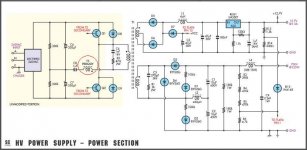
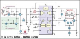
maybe somebody can help with this question. I found an article in Silicon Chip Silicon Chip Online - Regulated High-Voltage Supply For Valve Amplifiers where the old AT psu was modified to produce 400V high voltage for tube amp. The author has used the small current transformer for sensing primary current and therefore limit the current draw from secondary. In the schematic the T3 transformer is current sense transformer with the ratio 1:180, which reflects the primary side current 2V per amp. Its all understandable. What i dont understand, how the T3 transformer can be T2 transformer at the same time (on the picture) and use the same core which switches the output transistors? Shouldn´t the current affect the switching somehow? And sense the primary current also at the same time. Confusing....
I marked the transformer in red in schematics.
I actually built this unit and it works (mine is choozed 300V instead 400 or 700), but i really need some protection
Thank you in advance!
Attachments
I don't see anything wrong (although the schematics are a little hard to read). T2 is the base drive transformer and T3 is the current sense transformer. They are two separate transformers.
simple, picture is not the same as circuit in the schematic
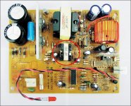
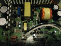
I really doubt that the picture and the schematic are not the same. I attached the pictures of my AT psu, which i modified and the second is already cleaned board, ready for rework. There is only small transformer in both boards which is transistor switch transformer, no current sensing one. Dont mind the small green toroid, its just the toroid from ATX psu i tried to act as current transformer (it doesnt work like that). I think those AT psus are design to sense current from secondary as voltage drop. I have 300V killing voltage on secondary and it is something i wouldn´t like to deal with 🙂. I think i have to try to wind some current transformer myself to sense the primary current.
Attachments
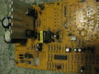

I just said in my previous post that dont look (mind) the green toroid 😀. I put it myself there to try it as current transformer. it has wrong ratio at this respect and it has not nothing to do with original circuit. Its even not connected on that picture youre referring to.The current transformer is here.
Modify the circuit to suit the current transformer on hand. There is no problem using the same sized core as both a current transformer and driver transformer, the flux in a current transformer is mainly determined by the secondary load and the core is sized to handle that. Ratio is not that important getting the correct voltage on the current sense line at the desired current limit is what you need to aim for. The resistor connected across the current transformer terminals is what determines that naturally there are limits and core saturation is the main one current transformers run into.
Modify the circuit to suit the current transformer on hand. There is no problem using the same sized core as both a current transformer and driver transformer, the flux in a current transformer is mainly determined by the secondary load and the core is sized to handle that. Ratio is not that important getting the correct voltage on the current sense line at the desired current limit is what you need to aim for. The resistor connected across the current transformer terminals is what determines that naturally there are limits and core saturation is the main one current transformers run into.
Thank you! This is the answer I waited 🙂. Its more convenient to wind one separate current transformer to sense primary current. I get into work now to see whether the smps will affect the sound of tube amp comparing to ordinary transformer.
Take care!
- Status
- Not open for further replies.
- Home
- Amplifiers
- Power Supplies
- current transformer in older AT psu-s