What has this to do with a current transformer (CT) ?
Looks like a saturable core flyback transformer.
Looks like a saturable core flyback transformer.
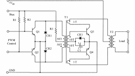
T1 works as a base drive transformer with the PWM source, and as a current transformer with the feedback from the output, probably to make sure that each transistor has completely turned off before the other one is allowed to turn on, even if the PWM signal is already active.
This mixed mode of operation makes the calculation somewhat more complicated than for either of the modes.
If you are unable to carry out the calculations by yourself, drop it because nobody is going to embark on such a chore for free. DIY help has some limits
This mixed mode of operation makes the calculation somewhat more complicated than for either of the modes.
If you are unable to carry out the calculations by yourself, drop it because nobody is going to embark on such a chore for free. DIY help has some limits
I spent almost two months to find out this transformer. I thought it just push-pull topology driver transfomrer.But Nothing on the internet.I am so Naive,HaHa,Thanks man.
I find the circuit in the book,named “Transformer and Inductor Design Handbook”,it doesn't explain the circuit.
I really want to master it ,Could you tell me some information or books to learn about it,If it is convenient for you.
Good luck to you.
I find the circuit in the book,named “Transformer and Inductor Design Handbook”,it doesn't explain the circuit.
I really want to master it ,Could you tell me some information or books to learn about it,If it is convenient for you.
Good luck to you.
The formula's for the windings are simple: N=V/(4*B*F*A) for the drive mode and N=L*I/(B*S) for the current sensing, but how do you combine the two?
Strikes me that it may be a form proportional base drive. Consider Q3. When it turns on top 1 turn dot goes positive enhancing the base drive to Q3... proportional to current? Same for Q4 the other/same way up. Not sure about CR3/C1 other than it might result in a clamped -Vbe drive for turn off of the non-active device.
PROPORTIONAL DRIVE CIRCUITS FOR BIPOLAR TRANSISTORS
Gosh I'm old.
PROPORTIONAL DRIVE CIRCUITS FOR BIPOLAR TRANSISTORS
Gosh I'm old.
Last edited:
Yes, it didn't occur to me, but it will also work that way (both modes aren't mutually exclusive).Strikes me that it may be a form proportional base drive.
It is in fact a self-oscillating converter synchronized by the PWM waveform, with probably most of the drive energy generated by the power side.
This article doesn't cover the calculation of transformersStrikes me that it may be a form proportional base drive. Consider Q3. When it turns on top 1 turn dot goes positive enhancing the base drive to Q3... proportional to current? Same for Q4 the other/same way up. Not sure about CR3/C1 other than it might result in a clamped -Vbe drive for turn off of the non-active device.
PROPORTIONAL DRIVE CIRCUITS FOR BIPOLAR TRANSISTORS
Gosh I'm old.
Current transformers were used in self-oscillating converter.T1 works as a base drive transformer with the PWM source, and as a current transformer with the feedback from the output, probably to make sure that each transistor has completely turned off before the other one is allowed to turn on, even if the PWM signal is already active.
This mixed mode of operation makes the calculation somewhat more complicated than for either of the modes.
If you are unable to carry out the calculations by yourself, drop it because nobody is going to embark on such a chore for free. DIY help has some limits
synchronized by the PWM waveform is too rare to find.
anyway,Thank you.
This article doesn't cover the calculation of transformers
Moan, moan, moan. Sigh.
Assume it is proportional base drive.
https://www.onsemi.com/pub/Collateral/MJE18008-D.PDF
Refer to the On characteristics.
Hfe is about 10 at IC=5A. Your secondary turns ratio becomes about 10, ratio of Ic/Ib, which you already have, 10Tbase/1Tcoll. If Hfe were 5 then 5Tbase/1Tcoll or 10Tbase/2Tcoll.
Your primary PWM has to overcome this current to switch the secondary device Off.
Assume the peak collector current is 5A. Base current is 500mA. With 50Tpri/10Tbase the required primary current is 100mA. If your bias voltage is 15V then, ignoring voltage drops, R3 needs to be about 150R to provide this current, pick 120R.
Vbeon is about 1.2V. Referred to the primary this will be about 6V. Say your switching frequency, Fs, is 50KHz. The period is 1/2Fs or 10uS. Your transformer has to support this volt-second product, 6V 10uS, without saturating.
Npmin = Vin.Ton/Bsat.Aemin
Rearrange
Aemin = Vin.Ton/Bsat.Npmin
Aemin = 6V x 10uS/0.3T x 50
Aemin = 40mm^2
That's the basics. You also have to worry about wire sizes and whether they will fit. All things are variable so you have to pick your own numbers and then iterate to find a core that works.
Oh.. If you want to be hard you might use the fact that push-pull operates in two quadrants so you can double Bsat.
Last edited:
An externally hosted image should be here but it was not working when we last tested it.
I really appreciate your help.
1.But like this picture,R46=1k5.It's not just a hundred ohms
2.The primary winding of the main transformer also appears to include the feedback winding of the drive transformer.Is that right?
I am sorry ,I don't explain clear.
1. The primary winding center tap of the drive transformer has a resistance of 1.5k, and the current reflected from the secondary winding should also be that many hundreds of milliamps, right?If you multiply it by that, isn't that much more than the 12V voltage provided by the primary?I'm a little confused.
2. Main transformer primary winding diameter (larger) + drive transformer feedback winding diameter (smaller), which together can just meet the size of primary collector current.Is it because of the series form in the circuit diagram that the wire diameter of the feedback winding does not need to be large?
I think you got wrong calculation,Ae=5mm^2Moan, moan, moan. Sigh.
Assume it is proportional base drive.
https://www.onsemi.com/pub/Collateral/MJE18008-D.PDF
Refer to the On characteristics.
Hfe is about 10 at IC=5A. Your secondary turns ratio becomes about 10, ratio of Ic/Ib, which you already have, 10Tbase/1Tcoll. If Hfe were 5 then 5Tbase/1Tcoll or 10Tbase/2Tcoll.
Your primary PWM has to overcome this current to switch the secondary device Off.
Assume the peak collector current is 5A. Base current is 500mA. With 50Tpri/10Tbase the required primary current is 100mA. If your bias voltage is 15V then, ignoring voltage drops, R3 needs to be about 150R to provide this current, pick 120R.
Vbeon is about 1.2V. Referred to the primary this will be about 6V. Say your switching frequency, Fs, is 50KHz. The period is 1/2Fs or 10uS. Your transformer has to support this volt-second product, 6V 10uS, without saturating.
Npmin = Vin.Ton/Bsat.Aemin
Rearrange
Aemin = Vin.Ton/Bsat.Npmin
Aemin = 6V x 10uS/0.3T x 50
Aemin = 40mm^2
That's the basics. You also have to worry about wire sizes and whether they will fit. All things are variable so you have to pick your own numbers and then iterate to find a core that works.
Oh.. If you want to be hard you might use the fact that push-pull operates in two quadrants so you can double Bsat.
It's a half bridge, your other circuit is push-pull. In the half bridge the return, other side of the transformer, is to the virtual mid rail through C7 to centre of C5/C6. The current winding in T2 carries a bidirectional current with the correct phase to enhance drive of the transistors. The push-pull needs two windings to recreate the correct currents.
I should have included the caveat that I am guessing with my big guess being that the drive has to turn the active device off which means completely overcoming the reflected base current. It may be the case and probably will be that it just has to be starved of sufficient current such that the collector current as scaled by hfe is no longer supported..
Ib = 1A hfe = 10 Ic = 10A
rob 100mA from Ib
Ib = 0.9A hfe = 10 Ic = 9A
still rob 100mA from Ib
Ib = 0.8A hfe = Ic = 8A
I'm suggesting the turn on and by extension turn off might be or is regenerative. As such I may/will have overcooked the required primary currents. Unfortunately you end up with more engineering decisions and if you err too far the other way then thing stop working.
Wire size is nominally down to carrying current. For general transformer design with convection cooling a figure of 4A per mm^2 is used but that can be varied. You might operate an exposed two turn winding at 8A per mm^2 or higher. Something with many more turns with less exposed windings or multiple layers may need lower current density.
It is more or less down to how well the winding is able to dissipate losses and where those losses come from. With low turns you might ignore losses due to proximity and layer effect. Skin depth, dpen, will still be important. With lots of turns/layers proximity and layer effect become important and the layers are less exposed.
Last edited:
- Home
- Amplifiers
- Power Supplies
- Current Transformer Deisgn