How much current would be needed to overcome a input capacitance of 6.5 uuF in order not to roll off the highs below say 30KHz?
To properly answer that question you would need to provide two more specs....
What is the source impedance..ie, what is the output impedance of where the signal is comming from ....also if it has output caps..provide those values...
Also you need to know the input impedance that is associated with this cap... Is there a input tube grid at this input also??? If so the miller cap needs to be accounted for as well...
All these R's and C's need to properly put togather into a equivelent circuit model..then you can properly calculate the frequency response....
The current you are refering to is proportional to the source output impedance.....
Chris
The source impedance does play a role in that it provides a voltage divider, but it has nothing to do with his question does it?
The current does however depend on the amount of voltage you need to slew at 30kHz. So if it at the output stage where you can have more than 100volts with low mu tubes, or at the input where you likely have less than 1volt at teh input you will have different currents (obviously).
Isn't the formula something like iC=(2*Pi*f*Amplitude)?
But remember the capacitance is not just the datasheet capacitance, but the stage's gain multiplied with the capacitance.
The output caps have nothing to do with this either.
Hmmm...it's been ages since I bothered to calculate such, so not sure I got this right, probably should have kept my mouth shut.
Think it is iC=(2*Pi*f*Amplitude*C)
Btw, uuF is today called pF.
Think it is iC=(2*Pi*f*Amplitude*C)
Btw, uuF is today called pF.
The slew rate limiting equation (5 time constants) when fully derived is equal to the -3dB POLE x 3.3 , I did the proof many years ago...
Lets say you want 20kHz to be free and clear from the slew rate limiting distortion...or it will be the boundary.... By putting the -3dB high frequency pole at 3.3 x 20kHZ , at 66kHz...puts 20kHz in the clear....
The only reason I wanted to know the output caps was for determining the low frequency roll-off...
The ouput impedance plays a major role in the high frequency roll-off... It is directly proportional to output current drive....
For the same given output amplitude...the lower Z has to source more current...
For proper calculation you really need to include the interconnects, since these have inductance and capacitance per foot that can be modeled as a lumped parameter Transmission Line...
Chris
Yes u are right. Its been a while since I last contemplated the issue. (It was interesting to me when designing with MOSFETs and after switching to tubes I havent worried about it).
The formula I mentioned for figuring the needed current for the given slew rate, is just a variation to the formula for capacitor impedance. Impedances and capacitances go into making low/high cutoffs so it just makes into a different view - same problem. Ohms law works either which way it is approached...
So basically he needs to know the max source impedance at 3.3*30kHz = 99kHz? Also find te actual capacitance, is there gain etc..
Well the source is a Cambridge audio 540P MM phono pramp. That doesn't really help does it? Here are the only specs they publish:
http://www.cambridgeaudio.com/specifications.php?PID=28&Title=Azur 540P Phono pre-amplifier
I suppose I could write them a email and ask for a little more info. The tube is a 6AS7.
http://www.cambridgeaudio.com/specifications.php?PID=28&Title=Azur 540P Phono pre-amplifier
I suppose I could write them a email and ask for a little more info. The tube is a 6AS7.
So u are coupling a 6AS7 to a 39dB gained phonostage huh?
At least u wont be bothering the neighbours😉
Should sound great thru headphones perhaps.
At least u wont be bothering the neighbours😉
Should sound great thru headphones perhaps.
Seriously G. U need not worry about the 6.5pF when u also have cables interconnects and such that totally dominate there.
What is it u are trying to achieve?
What is it u are trying to achieve?
SemperFi said:So u are coupling a 6AS7 to a 39dB gained phonostage huh?
At least u wont be bothering the neighbours😉
Should sound great thru headphones perhaps.
Let me 'splain. I only really need a gain of one from the linestage if I build the amplifier that I am thinking about. I do however need really low output impedance out of my preamp. I use my preamp to drive a subwoofer amp, which may have a input impedance as low as 10K and my amplifier with a input impedance of 100K. Both loads are in parrallel giving me a load of say 9K. The amplifier I am thinking about is a 396A driving a 6AS7. The 369A will be choke loaded and theoretically give me a gain of 35. The 6AS7 will be biased at -40 volts and 100mA.
How about removing C1 and replacing the plate choke with a cascoded 10M45S, using the low mu output?
zigzagflux said:How about removing C1 and replacing the plate choke with a cascoded 10M45S, using the low mu output?
I suppose the impedance of the load would be higher. It would also be cheaper. How much voltage would be dropped across the CCS @ 5mA?
OK, I'll jump in
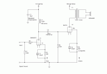
First, there seems to be a schematic error in the 6AS7 connections. Based on the circuit values I's guess it's supposed to be common cathode. Assuming that then...
The 100H is a little low but the 5670 has pretty low Rp (data sheet says 6k4 but it's closer to 9K at your OP. Calculated X(L) of the 100H inductor at 20Hz is approximately 12K so your fc is close to 20Hz. Real inductors seem to have more inductance than spec at low frequency though so it's probably fine; I'd measure it in the build.
Also at your OP for the 5670, in circuit voltage gain is 30 max. at mid frequency. Anode swing for 4Vp-p grid is 60V to 180V with a flat load line.
5ma might be considered a little light for a driver but looking at miller capacitance of the 6AS7 it's only (Cag=8p) * (1+Av=3) = 24pf + 6pf input capacitance. 30 pf plus the choke capacitance plus stray, maybe as much as 50pF depending on the choke. 5mA into 50pF results in 100v/uS slew rate so that checks OK (required slew rate for Vpk=40V at 40KHz is (Vpk * 2 * pi * f) or about 10V/uS.
The capacitive loading of your input stage is calculated the same way, which was I think your original question. Cag of the 5670 is 1.1pf so ((Cag= 1.1pf) * (1+Av= 31)) + (Cin=2.2pf) + 5pf stray = about 41pf. Your peak input voltage for full output will be 40/30 or 1.33Vpk. Slew rate at 40KHz for this is only 0.33V/uS. The peak current needed to drive this slew rate is about 15 microamperes.
EDIT: The input resistor contributes to the source loading also...
As already mentioned, interconnect capacitance will add a lot, figure 15pF per foot, somewhat less if you get fancy, but the peak drive current is still in the uA range for reasonable IC length.
I think everything else like anode dissipation, Rg, etc. look OK to me. I have no experience witth the 6AS7 re if it wants a grid stopper etc. though...
Cheers
Michael
A 10M45 would be an option, but would like to see a B+ high enough to cover your 40V signal swing plus a good 20V or more for the 10M45 (spec calls for Vd = 10V for 160K dynamic R). So B+ would need to be Vanode + 60V, say 190V+ for the driver.
Being a CCS, the voltage drop will be whatever it needs to be between B+ and anode voltage to maintain 5mA current. Anode voltage will be about the same at 130V or so. With B+ at 190V, the drop across the 10M45 will be 60 volts. It will dissipate 0.3 watts so no need for a heatsink.
Only issue I see is a practical one, how to easily generate driver B+ greater than the output stage B+
Michael
Looks like a very nice amp. I wouldn't change anything untill I'd listened to it.
...Perhaps one thing and that would be to give the input/driver tube the higher voltage and the 6AS7 the lower. The 6AS7 is very happy at low voltages, and 135volts is very spot on.
The 6AS7 needs about +-100Vp if you wish to get all available power out of it, and with more juice for the input you will get a little more swing. In terms of sound quality this tube is great even if you dont get to drive it all the way to max.
Ok. Here is the updated schematic with the recommended bump in B+ voltage. After the copper losses across the plate choke and the output transformer and the drop across both biasing resistors the plate voltages should be 175v for the 396A and 135v for the 6AS7G. I reduced the current through the output stage and increased the bias voltage at the cathode. I also increased the current through the 396A and increased the bias voltage to about 3.3v.
Attachments
- Status
- Not open for further replies.
- Home
- Amplifiers
- Tubes / Valves
- Current to overcome 6.5 uuF input capacitance?