I was playing around trying to remove the need for separate current sources for an input stage when I realized that base current compensated current mirrors are actually the combination of a current mirror and a two-transistor current source. This lead to the attached schematic.
The conundrum is: Why are R16/R17 needed? It simulates fine without them, but when built on a breadboard, the circuit will not turn on (no current through Q7/Q9). With the extra resistors added, it starts working the same as the simulation.
The conundrum is: Why are R16/R17 needed? It simulates fine without them, but when built on a breadboard, the circuit will not turn on (no current through Q7/Q9). With the extra resistors added, it starts working the same as the simulation.
Attachments
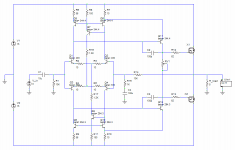
I don’t see why the circuit should start in the first place. The simulator must make certain assumptions when it starts running (or it models a very fast ramp up speed from the power supplies, kick starting the circuit through junction capacitance, or it assumes certain leakages in the devices that may or may not be present in the real devices at room temp). The presence of R16 & R17 in the breadboard may introduce enough spurious noise in the real circuit to initiate start up (I’ve seen that before in high impedance current source prototypes). Don't really know the answer for sure though.
Thanks for your thoughts.
I considered that perhaps the resistors in conjunction with the Early effect could give some positive feedback (reduced current through Q7/9 decreases the voltage drop across R16/17, increasing Vcb, which will tend to increase the current slightly because of the Early effect). To test this, I substituted R16/17 with Zener diodes, expecting that the circuit would fail to start with them, which is what happened.
I'm not sure if that really explains why it starts in the first place in reality but not in the sim. I tried simulating a slow ramp of the supply voltages but that didn't change anything. What is the simulator not taking into account?
I wouldn’t expect it to start with zeners in place either, as they would represent an additional potential to overcome for whatever marginal start-up mechanism is occurring.
With a Zener in series with the resistor it still starts, so that can't be stopping it, or at least not as much as whatever starting effect the resistor is having.
weird ... what kind of resistor and zener are they (not that that's going to enlighten me any)? Does it still start with no input signal present?
An ordinary metal film resistor and BZX55C 5V6 Zener. The tail current is about 5mA, so the voltage across the resistor is a bit more than the Zener - I'll do some tests later to see exactly what value of resistor is needed (I know 100R doesn't work, but 1K2 does).
I tested it with the input open, grounded, and with a signal (square wave) present, but that doesn't seem to make any difference.
Also, With the resistors removed, if I turn up the output stage bias by increasing RV1, I can get it to oscillate at about 0.5Hz, presumably it's repeatedly almost starting and then turning off again.
I'm not refusing, I'm experimenting.Lumba Ogir said:Mr Evil,
why do you refuse to supply suitable constant current sources for the LTPs?
On the contrary, I'm learning all the time.Lumba Ogir said:Not very fruitfully.
So do you have any idea what the resistors are doing, or what the cause of the discrepancy between simulation and reality is?
Oboy.
If that is a good current source, and it might be perfect,
then I never use anything but one resistor load.
Why make such a phreaking complicated addon to an amplifier.
Imagine if I design an amplifier which need several CCS
No, have a look at some good topics where we did a good ccs discussion last time.
ostripper and AKSA along we me, myself and a bunch of most clever other posters
had some good and fine normal ccs, when we finished our discuss.
That's where you go if you need the best investigated current source applications we know of.
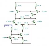
Without being as bloated and overloaded as the one we can see on submitted image.
Nice try, Lumba, but as being a swedish fellow
you can do better, I think
/yours linie
If that is a good current source, and it might be perfect,
then I never use anything but one resistor load.
Why make such a phreaking complicated addon to an amplifier.
Imagine if I design an amplifier which need several CCS
No, have a look at some good topics where we did a good ccs discussion last time.
ostripper and AKSA along we me, myself and a bunch of most clever other posters
had some good and fine normal ccs, when we finished our discuss.
That's where you go if you need the best investigated current source applications we know of.
Without being as bloated and overloaded as the one we can see on submitted image.
Nice try, Lumba, but as being a swedish fellow
you can do better, I think
/yours linie
lineup,
I certainly can, but it´s more than satisfactory for this kind of circuit with limitations.Nice try, Lumba, but as being a swedish fellow you can do better, I think
ostripper and AKSA along we me, myself and a bunch of most clever other posters had some good and fine normal ccs, when we finished our discuss.
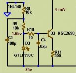
I won't overpost about this , but the simple LED/transistor (BLAMELESS) is all the CCS you might need. In the real world , with a single power supply, 300 watts of normal music content was run to one channel while listening to the other channel(ear right on speaker),in another room. NO AUDIBLE crosstalk between them was detectable.
The test amp was a large symasym at +-77v with 35k uF per rail x4,dual 35A bridges , single 1500VA trafo. Simulations and the scope show / predict 80-90db PSRR. I A/B'ed this setup with a total dual mono setup (2- 1500VA trafos) on the same amps while listening to both channels... NO AUDIBLE difference.
Zeners did not work as well as CCS's , I could hear crosstalk, even at mid level. My tests were slightly biased by the "supersized" PS and would expect slightly poorer results from a "normal" supply.
(test CCS attached)
OS
Attachments
Mr Evil said:
On the contrary, I'm learning all the time.
So do you have any idea what the resistors are doing, or what the cause of the discrepancy between simulation and reality is?
Does not need to be a discrepancy. Rule no. 1 if you can write down a consistent set of voltages and currents where a circuit does not start up it will find them on its own. 🙂 Try a pencil and paper walk through (output to input) and see if everything can sit there, off.
Sometimes a slow (or fast) transient analysis of a supply ramp can catch it too.
I appreciate that you're trying to help, but a schematic of an ordinary current source doesn't really help here.Lumba Ogir said:Mr Evil,
give it a try this way:
Yeah, there's no obvious path for current to flow initially, but that doesn't explain why it starts in the sims (it's not the supply voltage ramp speed, because I tried slowing that right down and it still switches on as soon as it reaches a threshold), nor why it starts in reality if the extra resistors are present.scott wurcer said:
Does not need to be a discrepancy. Rule no. 1 if you can write down a consistent set of voltages and currents where a circuit does not start up it will find them on its own. 🙂 Try a pencil and paper walk through (output to input) and see if everything can sit there, off.
Sometimes a slow (or fast) transient analysis of a supply ramp can catch it too.
If I can make the simulator match reality better then I can avoid this sort of problem in the future. And if I can understand better how the circuit is starting then I can hopefully alter it to deliberately cause it to start (in a better way than adding radom resistors).
Mr Evil,
the ideal current source properties are the same in any position. Why do you think your very common circuit would particularly represent an exception?
the ideal current source properties are the same in any position. Why do you think your very common circuit would particularly represent an exception?
- Status
- Not open for further replies.
- Home
- Amplifiers
- Solid State
- Current source conundrum