You're not getting the point. The point is that that 1 pA/sqrt(Hz) from the datasheet is not the spectral density of In1 and In2 but of their differential component (In1 - In2)/2. That reduces the discrepancy by a factor of sqrt(2).
I meant (in1 + in4 - in2 - in5)/2 of course, or (in1 - in4 - in2 + in5)/2 depending on how you define the directions.
there's no max in the ad797 datasheet , just the 2pa figure and there's a max 1.8pa in the lt datasheet...whatever...
You're not getting the point. The point is that that 1 pA/sqrt(Hz) from the datasheet is not the spectral density of In1 and In2 but of their differential component (In1 - In2)/2. That reduces the discrepancy by a factor of sqrt(2).
Not referring to any magnitude, why should a manufacturer specify uncorrelated Input Noise Current as a difference of (Inx minus Iny) divided by 2 ??
I can think of several ways to prove this can't be true, but I won't go into this.
When you're happy with this definition, I'm fine.
Hans
Because that is the noise form that will contribute to the output noise of an operational amplifier?...Not referring to any magnitude, why should a manufacturer specify uncorrelated Input Noise Current as a difference of (Inx minus Iny) divided by 2 ??
Hans
Not referring to any magnitude, why should a manufacturer specify uncorrelated Input Noise Current as a difference of (Inx minus Iny) divided by 2 ??
I can think of several ways to prove this can't be true, but I won't go into this.
When you're happy with this definition, I'm fine.
Hans
I don't think the manufacturer specifies uncorrelated noise current at all, but rather the differential noise current.
Three reasons to take half the difference between the momentary currents:
- It is a normal definition for differential current, because for a differential current output, it is the current that would flow through a floating load
- It results in a lower datasheet value than specifying the uncorrelated current.
- Most importantly, the equation for total noise in the LT1028 datasheet shows that this is the definition that Linear Technology has used.
Marcel, wasn't it you who calculated an unmatched current noise of 3.25pA/rtHz versus a matched current noise of 1pA/rtHz ?
Measuring phono stage RIAA accuracy with a computer
Anyhow this thread is not about figures but about the difference in matched versus unmatched behaviour of IBC amps.
Analog was not as specific with graphs as LT and also more honest with figures.
My next step will be to measure the LT1028, the same way I did with the AD797.
I'm looking forward to see how far they are apart.
In the image in #1 explaining the way how to achieve IBC, I used two independent PNP transistors, however I found that Scott mentioned in an earlier tread that this is likely to be a multi collector PNP.
To be honest, I have no idea how this translates into noise, but my assumptions are only to be seen as an attempt to understand things better.
The hard facts from measuring in the table at the end of #3, show what's really to be expected, wherever the noise comes from.
Scott mentioned also to never having measured a correlation coefficient better than 20%.
Without knowing the current noise of the amp without IBC this is hard to measure, that's where I used the 1pA/rthz assumption.
But again a 100% correlation seems absurd and that is what this thread is all about.
Hans
I calculated the 3.25 pA/sqrt(Hz) from a graph in the LT1028 datasheet, the 1 pA/sqrt(Hz) was copied from the spec table rather than derived from a graph.
I agree with you that the currents from a base current compensation circuit will never be completely correlated. They can't be, because some part of the circuitry is not common to the positive and negative inputs.
To what extent they are correlated will depend entirely on the internal circuitry of the op-amp. For an LT1028, I would expect a rather strong correlation, because the NPN that is used to generate the compensating current runs at a reduced current and the PNP mirror amplifies. That is, most of the noise comes from common circuitry.
On the other extreme, there are op-amps with completely separate base current compensation circuits for the positive and negative inputs. For those I would expect very little correlation.
By the way, as there are annotated currents in the schematic diagram in the LT1028 datasheet, you can simply calculate the shot noise densities sqrt(2 q I):
Base current shot noise of Q1 plus collector shot noise of Q7:
sqrt(2*2*q*4.5 uA) ~= 1.6982 pA/sqrt(Hz) with q ~= 1.6022E-19 C
This is the uncorrelated shot noise current. The differential current is sqrt(2) times less, so 1.2008 pA/sqrt(Hz) - already a bit higher than the specified 1 pA/sqrt(Hz), while second-order effects are not included at all.
Base current shot noise of Q13+Q14 plus collector shot noise of Q9:
sqrt(2*2*q*1.5 uA) ~= 0.98047 pA/sqrt(Hz)
This current gets amplified three times by the PNP mirror and is then injected into each input. Hence, this leads to a fully correlated noise current component with spectral density:
3*sqrt(2*2*q*1.5 uA) ~= 2.9414 pA/sqrt(Hz)
Total noise current per input:
sqrt((1.6982 pA/sqrt(Hz))^2 + (2.9414 pA/sqrt(Hz))) ~= 3.3964 pA/sqrt(Hz)
which is slightly higher than the 3.25 pA/sqrt(Hz) I got from a datasheet plot, even though second-order effects are not included.
Even though the dot is missing, I assume the emitters of Q1 and Q2 are connected.
Attachments

Last edited:
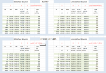
I finished doing the measurements as planned.
I had five pcs of LT1028, three LT1115 and four AD797.
Since all measurement where very close per type, I took their average and came to the following figures:
Voltage noise @1kHz
AD797 0.9nV/rtHz (0.9nV/rtHz spec)
LT1028 0.9nV/rtHz (0.9nV/rtHz spec)
LT1115 0.9nV/rtHz (0.9nV/rtHz spec)
Current noise Matched Resistors @1kHz
AD797 1.9pA/rt/Hz (2.0pA/rtHz spec)
LT1028 1.7pA/rtHz (1.0pA/rtHz spec)
LT1115 1.7pA/rtHz (1.2pA/rtHz spec)
Current noise Unmatched Resistors @1kHz
AD797 2.2pA/rtHz
LT1028 3.4pA/rtHz
LT1115 3.4pA/rtHz
As can be seen, I could not measure any difference in the voltage noise of the three contenders and they all performed exactly as their typical spec value.
There was also absolutely no measurable noise difference between the LT1028 and the LT1115 although the current noise of the LT1115 is 20% higher in the specs.
Quite unexpectedly, the current noise for the AD797 in the unmatched situation is only 1.3dB higher but for both LT's 6dB higher.
That can only mean that the correlation of the current noise in the IBC is much higher for the LT1028 and the LT1115 than it is for the AD797, no idea why.
This looks worse as it really is, because that will only become visible with higher values of Rs that are unlikely to be used with these amps.
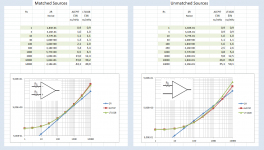
To show the relation between Rs matched / unmatched versus total Equivalent Input Noise, see the left image below.
The details of the calculations are in the right image.
In my search for the effect of IBC on matched/unmatched current noise, I had expected to find little difference between the AD797 and the LT1028, however the difference is much larger as I expected.
Especially Analog is very close with its specs to the real value, whereas LT is much more specific, but also much farther away from the real values.
Hans
I had five pcs of LT1028, three LT1115 and four AD797.
Since all measurement where very close per type, I took their average and came to the following figures:
Voltage noise @1kHz
AD797 0.9nV/rtHz (0.9nV/rtHz spec)
LT1028 0.9nV/rtHz (0.9nV/rtHz spec)
LT1115 0.9nV/rtHz (0.9nV/rtHz spec)
Current noise Matched Resistors @1kHz
AD797 1.9pA/rt/Hz (2.0pA/rtHz spec)
LT1028 1.7pA/rtHz (1.0pA/rtHz spec)
LT1115 1.7pA/rtHz (1.2pA/rtHz spec)
Current noise Unmatched Resistors @1kHz
AD797 2.2pA/rtHz
LT1028 3.4pA/rtHz
LT1115 3.4pA/rtHz
As can be seen, I could not measure any difference in the voltage noise of the three contenders and they all performed exactly as their typical spec value.
There was also absolutely no measurable noise difference between the LT1028 and the LT1115 although the current noise of the LT1115 is 20% higher in the specs.
Quite unexpectedly, the current noise for the AD797 in the unmatched situation is only 1.3dB higher but for both LT's 6dB higher.
That can only mean that the correlation of the current noise in the IBC is much higher for the LT1028 and the LT1115 than it is for the AD797, no idea why.
This looks worse as it really is, because that will only become visible with higher values of Rs that are unlikely to be used with these amps.
To show the relation between Rs matched / unmatched versus total Equivalent Input Noise, see the left image below.
The details of the calculations are in the right image.
In my search for the effect of IBC on matched/unmatched current noise, I had expected to find little difference between the AD797 and the LT1028, however the difference is much larger as I expected.
Especially Analog is very close with its specs to the real value, whereas LT is much more specific, but also much farther away from the real values.
Hans
Attachments
I assume you are using your own definition for the current noise with matched resistors again, rather than LT's definition, so corrected for that:
Current noise Matched Resistors @ 1 kHz
LT1028 1.2 pA/rtHz (1.0 pA/rtHz spec)
Current noise Unmatched Resistors @ 1 kHz
LT1028 3.4 pA/rtHz
Both quite close to the calculated shot noise, see post #28.
The AD797 presumably has a model transistor that runs at a higher current and less amplification in the PNP current mirror.
This looks worse as it really is, because that will only become visible with higher values of Rs that are unlikely to be used with these amps.
Have you seen the Elektor Supra 2.0 moving-magnet amplifier?
Zoekresultaten voor: 'Supra 2.0' - Elektor Four LT1028's in parallel in a moving-magnet amplifier, probably making this the highest noise moving-magnet amplifier ever, and a rather expensive one as well.
But quiet as a mouse with the input shorted?Have you seen the Elektor Supra 2.0 moving-magnet amplifier?
Zoekresultaten voor: 'Supra 2.0' - Elektor Four LT1028's in parallel in a moving-magnet amplifier, probably making this the highest noise moving-magnet amplifier ever, and a rather expensive one as well.
[ Been playing with ZTX851 low noise amps, its amazing to see something that makes the hiss from a 3 ohm metal film resistor distinctly louder than from a 1 ohm resistor. I made up an attenuator box with switchable output impedances 1-3-10-30-100-300-etc, and its a great quick diagnostic tool for assessing noise performance and input impedance of amp circuits - noise starts to rise when you match the equivalent noise resistance, output starts to drop when you match the input impedance ]
Interesting Hans. Maybe Scott can chime in - Scott?
Jan
My general feeling is why bother. I feel this noise correlation stuff is mostly bogus and has no relevance to any real application.
But again a 100% correlation seems absurd and that is what this thread is all about.
Hans
You bet this is absurd and I have never bought into it. Measure what you get and put it on the DS what else can you do.
One cannot make his "own" definition as LT's Marketing dept more or less shamelessly did to improve their noise current figures by a factor sqrt(2).I assume you are using your own definition for the current noise with matched resistors again.
You still don't seem to get that when the same current noise In flows through both matched resistors as they do in their calculation, they are by definition 100% correlated, which is 100% wrong.
Correlated currents will be cancelled by CMRR, no matter what twisted definition has been used.
There is only one physically correct way of calculating, of course not invented by me and that's also the one that obviously was used by Analog Devices.
Hans
And exactly that was the reason to start this thread, because the figures in LT's datasheet were full of inconsistenties.You bet this is absurd and I have never bought into it. Measure what you get and put it on the DS what else can you do.
Which has been confirmed here.
Hans
And exactly that was the reason to start this thread, because the figures in LT's datasheet were full of inconsistenties.
Which has been confirmed here.
Hans
The argument that the noise out of a split collector pnp is 100% correlated would require that all current generating mechanisms not be statistically independent which is physically impossible. At least if you use the published schematic. It also would ignore partition noise.
Hans, there is a much newer part that has even more unusual claims for current noise. I never got a chance to ask the designer before I retired.
Last edited:
One cannot make his "own" definition as LT's Marketing dept more or less shamelessly did to improve their noise current figures by a factor sqrt(2).
You still don't seem to get that when the same current noise In flows through both matched resistors as they do in their calculation, they are by definition 100% correlated, which is 100% wrong.
Correlated currents will be cancelled by CMRR, no matter what twisted definition has been used.
There is only one physically correct way of calculating, of course not invented by me and that's also the one that obviously was used by Analog Devices.
Hans
The key message of post #30 is that your LT1028 measurements match noise calculations based on the main shot noise sources with two figures accuracy. Using your definitions:
Current noise Matched Resistors @1 kHz
LT1028 1.7 pA/rtHz (sqrt(2) pA/rtHz spec)
Calculated in post #28: 1.6982 pA/sqrt(Hz)
Current noise Unmatched Resistors @1 kHz
LT1028 3.4pA/rtHz
Calculated in post #28: 3.3964 pA/sqrt(Hz)
I find it remarkable that measurement and theory are so close!
Regarding the definition matter, I would like to make one final attempt to figure out precisely where and why we disagree. I'll explain my point of view in the smallest steps I can come up with, so you can point out precisely where you start to disagree.
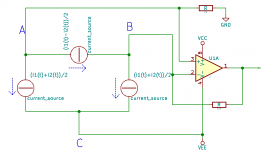
I've drawn a sketch with two time-dependent current sources, i1(t) and i2(t). I'm not making any assumptions about whether these are correlated, uncorrelated, correlated with a negative correlation coefficient or anything. They don't even have to have anything to do with noise, one might just as well be representing a Bach cantata and the other a Britney Spears song.
Do you agree that the circuit with three current sources drawn right next to it is an exact terminal equivalent? I think it is hard to deny this, because the current flowing through A, B and C is exactly the same for both circuits, but maybe you have a different point of view.
Assuming we can agree on this, do you agree that the two sources with value (i1(t)+i2(t))/2 have the same momentary value and are therefore fully correlated?
In the second picture, I've connected the three-source circuit to a simple op-amp circuit with equal resistances in the + and - branches.
Do you agree that the two sources with value (i1(t)+i2(t))/2 together have (to a good approximation) no influence on the output voltage of the op-amp?
Do you agree that therefore the source with value (i1(t)-i2(t))/2 is the only one that matters in this circuit with equal resistances in the + and - branches?
If so, then why do you consider it immoral to specify the spectral density of the only source that matters?
If you should have an issue with the fact that none of my three sources correspond 1:1 to a physical source (they all play a mix of Bach and Spears), then why do you accept equivalent input noise voltages? Physically, most of the LT1028's equivalent voltage noise comes from collector shot noise of the input transistors, so it is not physically generated at the input.
Attachments

- Status
- Not open for further replies.
- Home
- Source & Line
- Analogue Source
- Current Noise for OpAmps with Input Bias-Current Compensation