Is there a way to measure the current going through a power tube from the pins on the tube?
I am trying to figure a way to measure the current without having to pull the entire chassis out. I can measure the plate voltage by slightly pulling the tube up, and know which is pin 5 (6L6GC tubes) to measure the voltage.
I have thought about drilling a small hole, adding a rubber grommet, and using that as a test point for the B+, but I'd rather figure out a simpler method if possible.
Thanks,
Daniel
KatieandDad...
Can you please expand on that? The plate is the anode, but where is the resistance?
Can you please expand on that? The plate is the anode, but where is the resistance?
There MUST always be a load resistance between HT and the anode of the valve.
At the ouput valves this will be a transformer.
Unless it's in cathode follwer configuration.
At the ouput valves this will be a transformer.
Unless it's in cathode follwer configuration.
Last edited:
You need some means of either breaking into the circuit to connect an ammeter, or some known resistance as mentioned above to derive the current from the volt drop, or use "alternative" means that would be absolutely specific to the unit in question such as monitoring the whole HT current and then cutting of the valve in question and seeing how much the current reduced by. Is there a cathode resistor to measure across ?
There isn't always a load resistance to the anode if for example it's a cathode follower.
There isn't always a load resistance to the anode if for example it's a cathode follower.
Isn't that the plate voltage? I have the b+ voltage at 450 and the plates are at 445.
I'm not sure about what you are referring to. I have limited experience, especially with using testing meters. I have already blow 10 fuses in my meter because I either slip, or touch the wrong point because I don't know.
I know there is current flowing through the tube but don't understand why one cannot measure it there, or let me know if it can be done and how.
I would like to check-adjust the bias without opening up the amp.
Katie, you lost me...
How-or-can one measure the current from the pins of the tube?
If, yes, please explain how.
If, no, then I'm good with that.
Mooly, No, there is not. I have heard of a method using an exact 1 ohm resistor on the cathode, etc. but not sure if that would work this way or not.
How-or-can one measure the current from the pins of the tube?
If, yes, please explain how.
If, no, then I'm good with that.
Mooly, No, there is not. I have heard of a method using an exact 1 ohm resistor on the cathode, etc. but not sure if that would work this way or not.
Isn't that the plate voltage? I have the b+ voltage at 450 and the plates are at 445.
I'm not sure about what you are referring to. I have limited experience, especially with using testing meters. I have already blow 10 fuses in my meter because I either slip, or touch the wrong point because I don't know.
I know there is current flowing through the tube but don't understand why one cannot measure it there, or let me know if it can be done and how.
I would like to check-adjust the bias without opening up the amp.
If you are blowing fuses in the meter then it sounds like you are not understanding the method correctly. Sounds like you are shorting things out with the meter on a current range.
To measure current the meter must go in series with the anode (or cathode) circuit.
Post the circuit of the amp so we can see what it is and can advise better 🙂
I can't think of any way of measuring the current through a tube from its pins alone.
Mooly is driving you towards disconnecting (the anode - in most cases) pin and inserting a known resistor so that you can measure the voltage across that resistor.
An EXACT 1 Ohm resistor is a bit impractical. a 1% or 0.1% resistor of 1 or 10 Ohms would be sufficient to measure the current (as a voltage).
Mooly, No, there is not. I have heard of a method using an exact 1 ohm resistor on the cathode, etc. but not sure if that would work this way or not.
Yes, a 1 ohm (or any known low value resistor) in the cathode or anode would allow the current to be derived via ohms law.
Mooly, yeah, at first that's what I was doing, not understanding it fully, but yesterday I kept slipping and touch something else and blowing the damn fuse again.
That is why I wanted to do this, and not go in the amp.
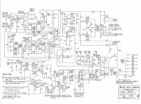
It's a Fender, here is a schematic...
Katie, I didn't mean 'exact', as there is really no such thing considering the equipment used to measure etc.
So this leads me to wonder if this will work without trying it and doing damage:
I would wrap a wire around the cathode pin, carefully without touching anything else, insert it in the socket, and attach that to a 1 ohm resistor and connect the other end to ground. Then, measure the voltage on the tube side of the resistor.
Would I be inviting something unwanted doing this?
That is why I wanted to do this, and not go in the amp.
It's a Fender, here is a schematic...
Katie, I didn't mean 'exact', as there is really no such thing considering the equipment used to measure etc.
So this leads me to wonder if this will work without trying it and doing damage:
I would wrap a wire around the cathode pin, carefully without touching anything else, insert it in the socket, and attach that to a 1 ohm resistor and connect the other end to ground. Then, measure the voltage on the tube side of the resistor.
Would I be inviting something unwanted doing this?
Attachments
So this leads me to wonder if this will work without trying it and doing damage:
I would wrap a wire around the cathode pin, carefully without touching anything else, insert it in the socket, and attach that to a 1 ohm resistor and connect the other end to ground. Then, measure the voltage on the tube side of the resistor.
Would I be inviting something unwanted doing this?
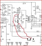
As you describe it, it wouldn't work because the resistor is just going across a wire (the cathode to ground link). For it to work correctly you would need to break the original cathode to ground lead and substitute with a resistor.
Now doing that would give a combined value as both valves run into the same point. So ideally you need two resistors, one in each cathode to be able to balance each value. With DVM's being able to measure accurately at low levels you could use really low values here that would have essentially no impact on the circuit or sound. Even values as low as 0.1 ohm would be OK given that most DVM's accurately measure in the low millivolts OK.
It's much safer doing this (resistor in cathodes) than measuring the anode current. You could wire the resistors to a couple of sockets somewhere so that the readings were always easy to get at.
Thanks, I see where my confusion was.
Unfortunately, I added a switch to go from fixed to cathode bias and I can't do this. I think I will make a point for the B+ and use the meter probe to pin 5. And, be cautious too.
Thank you everyone for all your help.
Unfortunately, I added a switch to go from fixed to cathode bias and I can't do this. I think I will make a point for the B+ and use the meter probe to pin 5. And, be cautious too.
Thank you everyone for all your help.
Just buy a commercial socket adaptor. Wrapping wires around tube pins is asking to electrocute yourself.
There are various products on the market with names like BiasRite, Bias King, BiasProbe, etc.
There are many ways to measure said current from the inside. You specified measuring without pulling the chassis. (Although MOST amps rquire pulling the chassis to ADJUST the bias regardless of how you measure current.) About the only way to do it externally is with a socket adaptor. The 1 ohm resistor in the cathode lead that people refer to is inside the socket adaptor.
You pull a tube from its socket, plug the adaptor into the socket, then install the tube into the adaptor. Wires trail off to your meter. Or to the base unit with its own meter. Essentially you are inserting the adaptor in series with the tube.
For example:
https://taweber.powweb.com/biasrite/br_page.htm
Compu-Bias™ Computerized Tube / Valve Bias Meter
Or just google "bias probe" and see what all pops up. If you look at a few of these options, you will see the common element is the socket adaptor, which you could make for yourself. Some of the google hits describe doing exactly that.
Thanks, I see where my confusion was.
Unfortunately, I added a switch to go from fixed to cathode bias and I can't do this. I think I will make a point for the B+ and use the meter probe to pin 5. And, be cautious too.
Thank you everyone for all your help.
The cathode bias resistor is in series with the two cathodes. Break the connection between the cathodes and the cathode resistor. Insert a 1 ohm resistor in each leg of the cathode of each tube. Run a wire out from the top of each resistor to a terminal. Run a wire to the bottom of the 1 ohm resistors to another terminal so you can measure across the resistors in either fixed or cathode bias mode.
Most are AC.Would a clamp-on current probe not work or is this all on a PCB?
- Status
- Not open for further replies.
- Home
- Live Sound
- Instruments and Amps
- current measuring