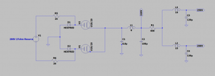
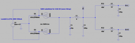
Looking for some advice here folks. I am building my first power supply, unregulated CLCLC. I will be using a 290V mains transformer with a calculated Rsource of 27ohms. The rectifier in this amp will be an old-timer, a GEC U18/20 in a hybrid diode bridge.
The GEC U18/20 spec sheet states a Rsource of 150ohm and max capacitance of 32uF at 350VAC.
Given my 132mA load, I have run the numbers and come up with a peak current of 330mA per anode (comes out to ~5x load current via the Radiotron Designer's Handbook method), well below the max peak current of 750mA for the U18/20.
I was hoping to avoid adding current limiting resistance between the transformer secondary and the rectifier, so I have used a small resevoir cap at 6.8uF.
How concerned do I need to be about a Rsource of 27 ohm and would anyone recommend adding these resistors? They would have to contend with the ripple current, would be large and hot, and I'd rather not go there if it isn't necessary. I've added a pair of 25ohm resistors in the schematic as an example.
Thanks!
Attachments
Last edited:
The Marconi datasheet rectifier design limits are 750mA and 2.75A.
Many of us use PSUD2 to get a quick view of the initial peak surge and continuous peak current levels, so as to compare against datasheet limits. Unfortunately PSUD2 doesn't directly simulate a hybrid bridge, or the U18-20, so some extra effort is needed to use it with some degree of confidence.
But even using a full bridge, if the secondary winding is only 290V, the rectifier is not going to be stressed no matter what the first filter capacitor is, or for any practical winding resistance.
Your model needs to identify choke ESR.
Is there any particular reason to use a U18-20, as it is quite a high voltage and high current rated diode so seems a bit of a waste in your proposed circuit. There is also no apparent need for any special silicon diode, as the valve diode will control the turn-off characteristic of the silicon diode, so a 1N4007 would likely achieve the same performance (or a UF4007 if you were sceptical).
Last edited:
The Marconi datasheet rectifier design limits are 750mA and 2.75A.
Many of us use PSUD2 to get a quick view of the initial peak surge and continuous peak current levels, so as to compare against datasheet limits. Unfortunately PSUD2 doesn't directly simulate a hybrid bridge, or the U18-20, so some extra effort is needed to use it with some degree of confidence.
But even using a full bridge, if the secondary winding is only 290V, the rectifier is not going to be stressed no matter what the first filter capacitor is, or for any practical winding resistance.
Your model needs to identify choke ESR.
Is there any particular reason to use a U18-20, as it is quite a high voltage and high current rated diode so seems a bit of a waste in your proposed circuit. There is also no apparent need for any special silicon diode, as the valve diode will control the turn-off characteristic of the silicon diode, so a 1N4007 would likely achieve the same performance (or a UF4007 if you were sceptical).
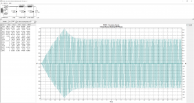
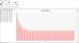
PSUD2 has an exact equivalent of the U18/20, the FW4-500. I have created this simulation using a full wave rectifier with transformer center tap. Assuming the "soft start" feature accurately simulates the warming of the rectifier, I am getting a inrush peak of 670mA at 0.5s and then the ripple current peak settles down to ~480mA. This is with no current limiting resistors (i.e., a simulated secondary resistance of 27ohm) and the choke DCR included. So if PSUD2 is to be trusted, it appears that no resistors are needed. In your experience, are these current values accurate?
It seems the 670mA peak agrees with my manual calculation of 330mA per anode with this setup, although perhaps I am overlooking something, I am new to this 😀
Attachments
Last edited:
L0rdGwyn - Noob question/suggestion here, so please disregard if wrong. In the model in your first post, is R1 (400R) meant to stand in for the DCR of L1 (150R) and L2/L3 (256R)? If so, shouldn't the DCR of L1 (150R) be represented by a resistor in series with L1 either directly before or directly after L1 - i.e., between C1 and C2? I think this will affect the performance of the filter model, including the actual value of the tap labelled 320V.
cheers, Derek
cheers, Derek
L0rdGwyn - Noob question/suggestion here, so please disregard if wrong. In the model in your first post, is R1 (400R) meant to stand in for the DCR of L1 (150R) and L2/L3 (256R)? If so, shouldn't the DCR of L1 (150R) be represented by a resistor in series with L1 either directly before or directly after L1 - i.e., between C1 and C2? I think this will affect the performance of the filter model, including the actual value of the tap labelled 320V.
cheers, Derek
Hi Derek - thanks for asking, sorry for the confusion.
In the LTSpice model, the DCR of L1, L2, and L3 is embedded within each inductor. The additional 400ohm of R1 is added to damp low-frequency ringing of the 15H LC filter. It also serves the purpose dropping the voltage for the 250V tap. This is for a single-ended class A design.
In all likelihood, it will not be as high as 400ohm, there is disagreement between PSUD2 and LTSpice as to how much resistance is needed to reach 250V. 100-200ohm will adequately damp the 15H LC filter, the value of R1 will be dialed in while testing the power supply.
Last edited:
Thanks for the clarification, and sorry for butting in. I mistakenly thought the value of R1 (400R) was suspiciously close to the combined DCR of L1 and L2/L3 (406R)- so thought I'd ask just in case.
The rectifier datasheet parameter for ia(surge) is the peak current allowed for a 'hot turn-on' event when the diode cathodes are hot, and the output stage valves are hot and conduct current as soon as voltage is applied. That is simulated in PSUD2 by not using a start up delay.
The rectifier ia(pk) is the continuous max peak level - so once supply voltages have settled and for a maximum loading scenario. With PSUD2 that is simulated with a reporting delay of say a few seconds and using a load resistance that pulls the highest loading current expected.
Any oscillatory response observed during start-up is of no consequence, and there is no need to modify circuit values to suppress. If you are concerned about power supply response, then PSUD2 can be set up to use a constant current load that can be stepped between two extreme current levels. If that extreme current step induces some oscillatory behaviour in the load voltage waveform then you have a concern.
The rectifier datasheet parameter for ia(surge) is the peak current allowed for a 'hot turn-on' event when the diode cathodes are hot, and the output stage valves are hot and conduct current as soon as voltage is applied. That is simulated in PSUD2 by not using a start up delay.
The rectifier ia(pk) is the continuous max peak level - so once supply voltages have settled and for a maximum loading scenario. With PSUD2 that is simulated with a reporting delay of say a few seconds and using a load resistance that pulls the highest loading current expected.
Any oscillatory response observed during start-up is of no consequence, and there is no need to modify circuit values to suppress. If you are concerned about power supply response, then PSUD2 can be set up to use a constant current load that can be stepped between two extreme current levels. If that extreme current step induces some oscillatory behaviour in the load voltage waveform then you have a concern.
Hi trobbins,
That clears things up quite a bit, thank for taking the time. Just to repeat back how I am understanding you, any brief surge even with a startup delay is safe assuming it is below the ia(surge) value of 2.75A. Once the voltages have settled, we are then concerned with the maximum continuous peak level. Assuming it is below 750mA for my U18/20, we are operating in a safe place for the rectifier
So in the photo in post #3 above, the 700mA surge on startup with the soft start and 500mA continous maximum current are well within the rated specification of the tube. Am I following correctly?
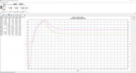
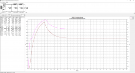
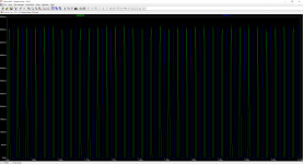
As for the ringing, I have done the procedure you reference using a current load and two extreme current levels before posting here. There is some minor ringing present from my observations, attached below. The first is without any additional series resistance with the 15H inductor, the second is with 250ohm series resistance with the 15H inductor.
As you can hopefully see, the ringing is well-damped with the addition of 250ohms. Whether or not this magnitude of ringing necessitates adding the resistors is beyond my understanding at the moment, but I am working to rectify that (no pun intended 🙂), but it will also likely help me dial in my 250V tap.
This resonance lives at 1/(2*pi*sqrt(LC)) = 3.6Hz
Attachments
Last edited:
Before giving my opinion, I'd like to know what the PSU is for. Some circuits are much more sensitive to DC stability than others. That aside, I have never had the need for more than one choke, and typically 1-2H. But again, my projects may be very different applications than yours.
Before giving my opinion, I'd like to know what the PSU is for. Some circuits are much more sensitive to DC stability than others. That aside, I have never had the need for more than one choke, and typically 1-2H. But again, my projects may be very different applications than yours.
This will be for a single-ended class A headphone amplifier. So low ripple is paramount and my understanding is that DC stability is not as critical in a SET design as the DC load current changes very little. Please correct me if I am mistaken! I am drinking from a fire hose these past few weeks. It is also worth noting that the 320V tap is going to a cascode CCS plate load, so the PSU is only in the signal path of the 250V tap to the output tubes.
Last edited:
Your interpretation of rectifier diode ratings is correct. Often the surge current rating is seen with a 200ms duration in the datasheet, and few power supplies exhibit a peak current above ia(pk) for that duration during hot turn-on. Your supply causes an initial peak of just over 1A, so well below the 2.7Apk rating. Even if you increased C1 from 6.8uF to 100uF, the hot-turn-on peak would still be just under 2.75A.
Perhaps easier to see a step change response by setting the step time to occur well after turn on (when everything is stable) - say at 2.1 secs. Then use a 2 sec reporting delay to allow the pre-existing levels to be seen as well as the response due to the step. The only noticeable oscillatory response is in L2 current with perhaps a frequency of about 10Hz (50ms from dip to bounce peak). So given you are operating class A, then a step power supply load disturbance would likely only happen if the amp was driven in and out of overload at about 10Hz, and likely would not cause such a large change in loading current (10 to 132mA steps). 10Hz is also not related to mains supply frequency. So I'd say it wasn't a concern, even if the simulation does not account for inductance variation or other non-ideal behaviours.
You will also notice that your output ripple is very low (<1mVpp), due to the use of two substantial chokes (given the 5W dissipation in the 15H choke).
Last edited:
Your interpretation of rectifier diode ratings is correct. Often the surge current rating is seen with a 200ms duration in the datasheet, and few power supplies exhibit a peak current above ia(pk) for that duration during hot turn-on. Your supply causes an initial peak of just over 1A, so well below the 2.7Apk rating. Even if you increased C1 from 6.8uF to 100uF, the hot-turn-on peak would still be just under 2.75A.
Perhaps easier to see a step change response by setting the step time to occur well after turn on (when everything is stable) - say at 2.1 secs. Then use a 2 sec reporting delay to allow the pre-existing levels to be seen as well as the response due to the step. The only noticeable oscillatory response is in L2 current with perhaps a frequency of about 10Hz (50ms from dip to bounce peak). So given you are operating class A, then a step power supply load disturbance would likely only happen if the amp was driven in and out of overload at about 10Hz, and likely would not cause such a large change in loading current (10 to 132mA steps). 10Hz is also not related to mains supply frequency. So I'd say it wasn't a concern, even if the simulation does not account for inductance variation or other non-ideal behaviours.
You will also notice that your output ripple is very low (<1mVpp), due to the use of two substantial chokes (given the 5W dissipation in the 15H choke).
trobbins - thank you again for your explanation. I have done what you recommended in PSUD2, and I agree, the waveform does appear to be 10Hz.
The overload scenario you described is very unlikely to happen. However, because the added resistance will also fine-tune my B+ for the output tubes (which should really be ~284V out of the supply, as I am aiming for a 250V anode voltage with 16V on the cathode and a 18V drop across the output transformer primary), I am inclined to include it and damp the resonance anyway, even if it is essentially harmless
Some trial and error has given me the final design below. I have replicated a single channel of the power supply in PSUD2 and I am getting near perfect agreement with LTSpice. With 400ohm in series with each 15H inductor, I reach a near critical damping ratio of 0.965. Step response in PSUD2 shows no ringing. With this added resistance I am getting a near perfect 284V B+ rail, meaning I will have my 250V on the plate of the output tubes.
I have been working on this supply for a very long time. Unless there is some error I am overlooking, I feel it is FINALLY complete 😀
(please note a 5AR4 model has been used in LTSpice as it has the same voltage drop as the U18/20)
Attachments
Last edited:
trobbins, if I could tap your experience one more time please...
While the power supply I described above would be ideal, there is one aspect of the LTSpice model that is worrying me and I am suspicious of my interpretation.
From the manual calculation I had done of peak and average current per anode, I should be seeing the following approximately for a full-wave rectifier:
Ia(avg) = ~I(DC load)/2 = 132mA/2 = 66mA (this agrees with LTSpice model)
Ia(peak) = ~Ia(avg)*5 = 330mA per anode
(this is following the method in the "Rectification" section of the Radiotron Designer's Handbook)
This would seem to suggest that the peak current per anode is divided in half, similar to the average, when viewed at 60Hz.
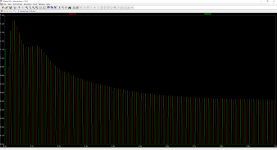
But when viewing the waveform in the LTSpice (pictured below), from my interpreation, both halves of the rectifier are seeing the same Ia(peak), which is the crest of the waveform, but at 60Hz each rather than 120Hz.
Perhaps my understanding of peak current is incorrect. Is the Ia(peak) specification only considered at 120Hz and halved at 60Hz? The Ia(avg) value makes sense, as half of the current waveform is lost due to half-wave rectification for each anode, but how can the peak value differ between 60Hz and 120Hz? I hope my conundrum is making sense.
The bottom line is I am not sure if I would be comfortable with a 612mA per anode peak current with a maximum specification value of 750mA per anode and would consider adjusting the circuit to give more headroom, but I am not trusting my interpretation of peak current per anode, as it very well may be closer 306mA per anode Ia(peak) following the RDH method.
While the power supply I described above would be ideal, there is one aspect of the LTSpice model that is worrying me and I am suspicious of my interpretation.
From the manual calculation I had done of peak and average current per anode, I should be seeing the following approximately for a full-wave rectifier:
Ia(avg) = ~I(DC load)/2 = 132mA/2 = 66mA (this agrees with LTSpice model)
Ia(peak) = ~Ia(avg)*5 = 330mA per anode
(this is following the method in the "Rectification" section of the Radiotron Designer's Handbook)
This would seem to suggest that the peak current per anode is divided in half, similar to the average, when viewed at 60Hz.
But when viewing the waveform in the LTSpice (pictured below), from my interpreation, both halves of the rectifier are seeing the same Ia(peak), which is the crest of the waveform, but at 60Hz each rather than 120Hz.
Perhaps my understanding of peak current is incorrect. Is the Ia(peak) specification only considered at 120Hz and halved at 60Hz? The Ia(avg) value makes sense, as half of the current waveform is lost due to half-wave rectification for each anode, but how can the peak value differ between 60Hz and 120Hz? I hope my conundrum is making sense.
The bottom line is I am not sure if I would be comfortable with a 612mA per anode peak current with a maximum specification value of 750mA per anode and would consider adjusting the circuit to give more headroom, but I am not trusting my interpretation of peak current per anode, as it very well may be closer 306mA per anode Ia(peak) following the RDH method.
Attachments
Last edited:
P.S. A mistake was made in the schematic above in post #13, the substituted rectifier for the U18/20 was meant to be the 5U4G with a Vdrop of 33V, not the 5AR4! Some adjustments have been made, but the design holds overall and my question in post #14 stands.
Last edited:
Are you able to post the PSUD2 screen that compares to your LTSpice plot?
Each diode does indeed conduct at 16ms intervals (60Hz), but the transformer winding, and output filter sees current pulses at 8ms interval (120Hz) with the transformer winding experiencing alternating (AC) current pulses. The valve diode datasheet rating is for the peak current level of each pulse that the diode experiences (with no requirement for those peaks to be of any particular frequency/interval, so they don't refer to an average or rms value).
This is somewhat similar to a silicon diode spec that has a peak current rating - eg. a 1N4007 has a 30A pk rating, although that rating has different proviso's attached to it than a valve diode would have.
Some general reading on this topic area is in:
https://www.dalmura.com.au/static/Power%20supply%20issues%20for%20tube%20amps.pdf
Are you able to post the PSUD2 screen that compares to your LTSpice plot?
Each diode does indeed conduct at 16ms intervals (60Hz), but the transformer winding, and output filter sees current pulses at 8ms interval (120Hz) with the transformer winding experiencing alternating (AC) current pulses. The valve diode datasheet rating is for the peak current level of each pulse that the diode experiences (with no requirement for those peaks to be of any particular frequency/interval, so they don't refer to an average or rms value).
This is somewhat similar to a silicon diode spec that has a peak current rating - eg. a 1N4007 has a 30A pk rating, although that rating has different proviso's attached to it than a valve diode would have.
Some general reading on this topic area is in:
https://www.dalmura.com.au/static/Power%20supply%20issues%20for%20tube%20amps.pdf
Thanks for posting that reference, I will read it this evening.
Below are the comparable LTSpice and PSUD2 plots for the Ia(peak) current at startup. Some minor changes have been made (having accidentally used a 5AR4 in my LTSpice model); the 15H series resistance has been reduced to 225ohm and I have used a 5U4G in both programs for the sake of comparison, similar results for the U18/20 in PSUD2. Some of the downstream voltages now do not agree between the two models, but the pattern for ripple current agrees almost perfectly, with 520mA Ia(peak). I think the higher Ia(peak) value I was coming up with before was in part due to accidentally using the 5AR4 rather than the 5U4G as a U18/20 substitute in my LTSpice model. If 520mA is the true estimated Ia(peak) per anode, I think that leaves a comfortable amount of headroom for the U18/20 to work with.
Using the FW4-500 in PSUD2, which is an exact U18/20 equivalent, yields an Ia(peak) of 490mA, so I think I am in good shape! Thanks for the explanation.
Attachments
Last edited:
- Home
- Amplifiers
- Tubes / Valves
- Current Limiting Resistors b/w Transformer Secondary & Tube Rectifier