Hello, I am having an issue with an amp I'm rebuilding. It is a 6aq5 single ended stereo amp, RCA I believe. I don't have a schematic.
The problem is one side has little or no volume. They are both wired exactly the same, each has its own 12ax7 preamp feeding a 6aq5. I measure the current on the good side and the sound cuts out completely. But after much searching I noticed that when I measure the current on the bad side the volume does not cut out at all. I believe that's the problem, but I don't know why. Is the transformer bad? It has continuity in the primary and secondary, and the current measures close to the good side, only the sound does not cut out.
Suggestions please, thanks,
Daniel
I've no idea what you mean by 'measure the current', or why you want to do such a thing?.
Current measurement is an unusual and rare event in amplifier repair, particularly valve ones - almost everything can be checked with simple non-invasive voltage measurements.
For a start measure the voltages on the anode and cathodes of the 6aq5's, and the anodes of the 12ax7 - by FAR the most common fault in valve amplifiers is failure of the anode loads of the triodes.
You don't really need a circuit, it's a very crude and simple design.
If the sound goes away when you try to measure (something) on the "good" side, it sounds like the side that is working stops working when you take a measurement. That means either you are not taking the measurement correctly, or perhaps the amp is breaking into RF oscillation and spends all its energy trying to do that and can't pass audio.
Without being there, my vote is your technique has an error. As Nigel said, I don;t see the need for current meaurements. About the only current you might want to know would be power tube plate current, and since it is a simple single ended amp, you likely have a cathode resistor. That means a voltage reading across that provides current by using Ohm's Law.
Since the good channel acts this way, and the bad channel doesn;t, I suspect the reason is that your bad channel is not working, so there is nothing for the measurement technique to screw up.
I also agree that a schematic probably is not necessary, but for you, I think a good exercise would be to draw one from the circuit. Take a sheet of paper, and across the center draw two triode symbols and one pentode symbol. If all your tube heaters are lighting up, don;t even bother tracing out the heaters. Next to each tube symbol, we will mark the pin numbers. ANy 12AX7 and 6AQ5 data sheet will tell you the pins.
Now follow from each tube on the amp where each part goes and what it connects to. The result will be a schematic. It should wind up looking similar to this:
http://www.webphix.com/schematic heaven/www.schematicheaven.com/fenderamps/champ_5e1_schem.pdf
I'd also agree with taking the basic voltage readings around the tubes. Whatever your high voltage might be, 300-350v maybe, you ought to find it on both pins 5 and 6 of the 6AQ5, and pins 1 and 6 of the 12AX7 ought to have high voltage as well.
As Enzo says, drawing the circuit out would be a very good idea.
Maybe you mean "measure voltage" rather than "measure current" ? You do need to distinguish between the two, or your meter will die very quickly
Maybe you mean "measure voltage" rather than "measure current" ? You do need to distinguish between the two, or your meter will die very quickly
Hmmm. I can't understand why you guys say not to measure the current. I am measuring the plate current by what I believe is the shunt method. I put one probe on the b+ and the other on the plate. All my amps that I've worked on or built I have done this. Why is that any different than measuring voltage wrt to danger. The plate has 240 volts on it. On my 50 watt amp it has 450 volts. I measure the current to make sure I'm in line with the plate dissipation between 60 and 70 percent. According to what I read, that is optimum, even on the weber calculator online.
And, yes, I have shorted out my meter by being careless with the probe with it slipping or just forgot it was in current mode and blew fuses. That is what the fuse is in there for, to protect the unit from stupid mistakes among other things.
Any time I measure the current this way, which is what is described in Gerald Weber's book and Aiken Amps pages, it cuts out the sound completely.
Nigel: You have said that in my other inquiries before and I think you are wrong. Measuring plate current is necessary. I did measure the voltages on the plates and screens, and they are fine, 240v and 239v respectively. I know there are other ways like the one ohm resistor on the cathode end and it's safer but I'm not worried. Sure I've blown some fuses and scared myself, but that's how I learn.
Simon: What other type of current would one measure other than plate current? Does one need to be so specific? I really don't think so. And, contrary to your comment about my meter dying, it is the fuse that dies if I screw up.
I have some knowledge of what I'm doing but I don't have much experience in troubleshooting.
Enzo: I really respect your comments as you usually know what I am talking about with previous questions I've asked. Your answers are always right on. Plate current is what I am measuring, I thought that would be self evident since there isn't any other current I've heard about to measure.
I am measuring the plate current correctly. No doubt. I have done it before and the hum, hiss, etc 'shorts' out when I touch the probes of my meter to the b+ and plate pin. But on this one side, which is very distorted and very low volume compared to the other one, it does not. That is why I suspect the transformer. I could just swap it out but I thought I'd ask the question to have more knowledge. It took me a long time to discover that was going on.
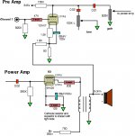
Here is a schematic:
And, yes, I have shorted out my meter by being careless with the probe with it slipping or just forgot it was in current mode and blew fuses. That is what the fuse is in there for, to protect the unit from stupid mistakes among other things.
Any time I measure the current this way, which is what is described in Gerald Weber's book and Aiken Amps pages, it cuts out the sound completely.
Nigel: You have said that in my other inquiries before and I think you are wrong. Measuring plate current is necessary. I did measure the voltages on the plates and screens, and they are fine, 240v and 239v respectively. I know there are other ways like the one ohm resistor on the cathode end and it's safer but I'm not worried. Sure I've blown some fuses and scared myself, but that's how I learn.
Simon: What other type of current would one measure other than plate current? Does one need to be so specific? I really don't think so. And, contrary to your comment about my meter dying, it is the fuse that dies if I screw up.
I have some knowledge of what I'm doing but I don't have much experience in troubleshooting.
Enzo: I really respect your comments as you usually know what I am talking about with previous questions I've asked. Your answers are always right on. Plate current is what I am measuring, I thought that would be self evident since there isn't any other current I've heard about to measure.
I am measuring the plate current correctly. No doubt. I have done it before and the hum, hiss, etc 'shorts' out when I touch the probes of my meter to the b+ and plate pin. But on this one side, which is very distorted and very low volume compared to the other one, it does not. That is why I suspect the transformer. I could just swap it out but I thought I'd ask the question to have more knowledge. It took me a long time to discover that was going on.
Here is a schematic:
Attachments
Last edited:
Hmmm. I can't understand why you guys say not to measure the current.
Because you have to disconnect things in order to insert the meter, and it generally tells you nothing that the voltage reading doesn't.
Nigel: You have said that in my other inquiries before and I think you are wrong. Measuring plate current is necessary. I did measure the voltages on the plates and screens, and they are fine, 240v and 239v respectively. I know there are other ways like the one ohm resistor on the cathode end and it's safer but I'm not worried. Sure I've blown some fuses and scared myself, but that's how I learn.
I've been repairing amplifiers for 41 years professionally, and before that as an amateur - I doubt I've ever measured current through a valve in all that time, it's really not something you ever have to do. True, you do have to set bias adjustments occasionally, but amplifiers are almost always designed to do so with a simple voltage measurement.
In the circuit you posted both valves have cathode resistors, measuring the voltages across those will tell you the current through the valves.
The other obvious question is which stage is giving you the problem?.
What are the cathode voltages?
The power stage is giving me problems. The cathode voltage is 11.36v and the cathode is shared with the other 6AQ5. That means that 11.36v/128.5 ohms (measured) = 88.4mA. So for both tubes that should be 44.2mA each.
I measure the current by the shunt method. Here are two links that describe it:
On page 105:
A Desktop Reference of Hip Vintage Guitar Amps - Gerald Weber - Google Books
Second bullet in Plate/Cathode Current Method:
Biasing
And I don't need to disconnect anything either. I measure the current by the above method to be 22.6mA on the bad working side and 21.7 on the good working side. The plate voltages are: 243v and 244v respectively. Also, the screen currents are 14.2mA and 14.5mA respectively. Add all those up and I get 36.8mA on the bad side's tube and 36.2mA on the good one. That's almost 8mA different than my calculation above. Assuming I am calculating the current correctly. The only other thing I can think that would result in a difference is the capacitive resistance in the bypass cap I have. It is a 47uF/50v, the schematic is incorrect on that, I just noticed.
But, I would like to address my original question concerning the sound not cutting out using the shunt method with the side that is not working properly. I really don't need advice on what method I'm using. It is what I chose because it is easy and it is what others use too. My meter is a Vellman, a good quality one, not a Fluke, but not a Radio Shack one either.
I can open another thread and title it: 6AQ5 plate current using shunt method issues
Should I? And, are you familiar with the shunt method for measuring the plate current?
Thanks,
Daniel
Last edited:
In the guitar amp world the shunt method is used by some. Setting the meter to current, and putting it parallel to the OT primary winding, the very low internal resistance of the meter takes all the current, or at least the majority of it, bypassing the winding. Maybe not the most accurate but it generally works.
However, putting meter leads on the plate wires also can act as a great antenna, radiating all around. SO SOMETIMES touching a meter probe to a power tube plate can couple the plate signal to other stages, causing oscillation. SO using other methods just to avoid that is a wise move. Any time a reading is funny or a circuit reacts, it is a good idea to try to get the same information another way, just to see.
When you shunt the transformer winding, the tube current is no longer flowing through it, so don't expect the amp to continue to function normally while you are on there. That style of current reading is ONLY good for finding tube current. It is not compatible with troubleshooting signal issues. When I take such a reading, I expect while the probes are on I will get a hummy sound from the speaker, and very likely HF or RF oscillation.
I would not normally use that method with a cathode biased amp, but since your two channels share a cathode resistor, I suppose the reading across it being for two tubes, you then don;t know if they are sharing equally or if one tube is hogging the current.
If one measures current through the cathode, one needs to consider the contribution of screen grid current. That is the other current one might want to consider. You wondered.
You mention 70%. Well, that is only a rule of thumb that many rely upon, but it certainly is no requirement. And that is generally for the common class AB push pull amps. Your amp is a single ended amp, and as such is going to be running class A. Class A power amps usually run at much higher idle dissipation. The 70% rule doesn;t apply.
A shared 125 ohm cathode resistor? You can disconnect it and install a 250 ohm for each tube. That will break any intereaction, at least at the cathode. Put it back the other way when the problems are all resolved.
Well I found the problem. But I don't know why it was an issue. I had used a shielded wire coming from the volume pot to the .02 cap that feeds the 6AQ5 tube. For some reason I unhooked it to do something and didn't bother reconnecting it and the damn thing worked. The other side was so short I just used the cap leads. I ended swapping the transformer but not it. Switched speaker jacks, not it. Switched inputs, not it, took of the feedback line, not it. I was about to switch volume pots but forgot about something and then discovered the shielded wire was the problem.
Why???
Enzo, I use between 60 and 70% as a rule for my amps so far and like the response I get. I forgot that single ended is no more than 90% though. In the future I will try using two cathode resistors for better balance too, that's a good point about the hogging of one side vs the other.
Could that 8mA difference in math vs measurement per side be the result of the meter? That seems like a high error.
And thanks for all your help...
.....Simon: What other type of current would one measure other than plate current? Does one need to be so specific? I really don't think so.
Mostly I measure current in gear like this by measuring voltage across a resistance. Including the dc resistance of transformer windings.Maybe you mean "measure voltage" rather than "measure current" ?
Glad your meter's still good. I've knackered one with that mistake, I was hoping to save you that problem. Mine blew the fuse, but blew the current circuit too - the fuse wasn't fast enough, that happens. On the other hand I've yet to blow a voltage range on any meter. Though no doubt that will change tomorrow, seeing how I've just opened my mouth.....😀.....And, contrary to your comment about my meter dying, it is the fuse that dies if I screw up.
.....Any time a reading is funny or a circuit reacts, it is a good idea to try to get the same information another way, just to see......
This should carved in stone and stuck on the side of spaceships.

Stone spaceships? Hmmm. So its a rock-et?
(Thank you, thank you, I'll be here all week, you folks have been great. Try the veal.)
(Thank you, thank you, I'll be here all week, you folks have been great. Try the veal.)
- Status
- Not open for further replies.
- Home
- Live Sound
- Instruments and Amps
- current issue