Hello,
Recently i was thinking about current drive, high output impedance and tewbs. In the interest of not derailing the question of the thread with why current driving sucks and we want damping and everything was designed with voltage drive in mind and so on, lets just take it as a premise that's what we want to do, hypothetically.
Normally we take the current out of a dac, turn it into a voltage (transimpedance), then amplify it, and so on, to the load it goes.
There are amplifiers that take the line out voltage and output a current, so the current is constant and the voltage varies (transconductance amp).
But what about taking out the middleman, never doing I/V, and using the current straight out of the DAC and just adding some gain with an opamp or whatelse to drive some headphones for example?
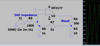
I mention opamps just because that's what i tried to build in LTspice, however i couldn't find a configuration that does what i want. In fact havent even really found any circuit for this out there, leading me to believe im embarking on something silly, or that of course the opamp might not be the thing i need for this, despite its many conveniences. In the attachment find the best i managed but it a bit fishy and not sure how to null it without a servo or something, since cant put a DC blocking cap in the loop.
Since this is DIY, i hope you can humour this concept, so in this thread i ask the basic 2 questions:
1. If we want to current drive something (say some headphones), why not start at the source and just add some gain to the current of the DAC, instead of doing I/V and then V/I?
2. If this can be done, how?
Regards,
Recently i was thinking about current drive, high output impedance and tewbs. In the interest of not derailing the question of the thread with why current driving sucks and we want damping and everything was designed with voltage drive in mind and so on, lets just take it as a premise that's what we want to do, hypothetically.
Normally we take the current out of a dac, turn it into a voltage (transimpedance), then amplify it, and so on, to the load it goes.
There are amplifiers that take the line out voltage and output a current, so the current is constant and the voltage varies (transconductance amp).
But what about taking out the middleman, never doing I/V, and using the current straight out of the DAC and just adding some gain with an opamp or whatelse to drive some headphones for example?
I mention opamps just because that's what i tried to build in LTspice, however i couldn't find a configuration that does what i want. In fact havent even really found any circuit for this out there, leading me to believe im embarking on something silly, or that of course the opamp might not be the thing i need for this, despite its many conveniences. In the attachment find the best i managed but it a bit fishy and not sure how to null it without a servo or something, since cant put a DC blocking cap in the loop.
Since this is DIY, i hope you can humour this concept, so in this thread i ask the basic 2 questions:
1. If we want to current drive something (say some headphones), why not start at the source and just add some gain to the current of the DAC, instead of doing I/V and then V/I?
2. If this can be done, how?
Regards,
Attachments
Last edited:
Attachments
Short R9 and you're there.
With R9 you're trying to turn a current into a voltage again and you don't want that.
The DAC current flows into R7 and that creates the opamp output.
Jan
With R9 you're trying to turn a current into a voltage again and you don't want that.
The DAC current flows into R7 and that creates the opamp output.
Jan
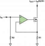
Since you posted a Spice schematics, I trust you can finish the simulation yourself.
It only means to demonstrate the principle.
For best results, you need to find better complementary transistor pairs.
See also:
https://www.diyaudio.com/community/...per-linear-transconductance-amplifier.328449/
Cheers,
Patrick
.
It only means to demonstrate the principle.
For best results, you need to find better complementary transistor pairs.
See also:
https://www.diyaudio.com/community/...per-linear-transconductance-amplifier.328449/
Cheers,
Patrick
.
Attachments
Last edited:
Short R9 and you're there.
With R9 you're trying to turn a current into a voltage again and you don't want that.
The DAC current flows into R7 and that creates the opamp output.
Jan
Short R9 and preferably remove R8, as it doesn't do anything useful and only injects noise.
Yes. Opamp 101: in normal operation, the opamp inputs are at the same potential. Almost, not quite, but close enough for back of the envelope calculations.
Also, you can assume there is no current going into an input.
In the original circuit, the + input is at ground, so the -input is also at (almost) ground. So R8 is connected between two ground point and doesn't do diddly.
Similar reasoning can be used to calculate the output voltage. The DAC output current flows through R7 only. With R7 = 51 ohms, and a DAC output current of say 2mA, there's 102mV across R7. One side of R7 is grounded, so the other side has the 102mV signal, and this is the output signal.
Make R7 1k and the output is 1V per mA DAC output current.
Easy ;-)
Jan
The output signal is the current through Rload, which is -(1 + R7/R5) times the input current, or 1 + R7/R5 times the input current, depending on what you call the positive terminal of Rload.
Jan,
It is supposed to be a current amplifier, not transconductance (IV conversion).
Please check out post #5.
RL is the headphone.
But it needs 4-wire connection (no common Gnd).
Cheers,
Patrick
It is supposed to be a current amplifier, not transconductance (IV conversion).
Please check out post #5.
RL is the headphone.
But it needs 4-wire connection (no common Gnd).
Cheers,
Patrick
-(1 + R7/R5) times the input current, or 1 + R7/R5 times the input current
1+(R7/R5), or just R7/R5 ?
Both free ends of R7 & R5 at Gnd / virtualGnd.
Cheers,
Patrick
If you want to ground one side of the load, you need an active part with a floating output port. A way to do that with op-amps, is to use floating supplies and connect the centre to the load.
For example, use two 9 V batteries to supply the op-amp and tie the point where they are connected to each other to the headphone, with the other terminal of the headphone grounded. For a stereo amplifier, you need four batteries.
Instead of batteries, you can also use floating mains supplies, if the capacitance between the mains and the output is small enough.
Hello, thank you everyone for the replies. I've been reading a lot of material since starting the thread and trying what you've suggested , sorry i havent replied back earlier. I've been looking at Howland current pumps and then got sidetracked to the chipamp side of the forum.
With R9 i was trying to simulate the output impedance of a TDA1541 (most R2R seem to be in the ballpark i think too), so it wasnt really an active part in the circuit i guess, but i see in EUVL's representation, to use a voltage source and then a resistor after it.
I was reading about your super linear thread before making mine, i searched around the forum, but i havent seen it in the I -> I configuration, that's cool. Thank you Patrick for the spice files, yes i finished the first simulation, i guess. i wasnt able to use the voltage source+resistor as the representation for the DAC Iout like you set up in the other one, as the simulation is just stuck at 0.0%, and with a current source its oscillating or at least something is wrong with the fft.

Probably i messed up something. If i replace the 5mA CCS with your 2sk209 CCS (on the left) it also doesnt really work, so i must suck at this.
I like the simple IC solution too but like the one in OP, there's a volt or so of DC offset. It even keeps switching polarity as load impedance is increased? At 50R its -2V, at 100R 1.8V, at 500R -0.75R. maybe its an ltspice quirk.
Anyway with all these questions i realise competent enough for this and there's too much stuff going on so im realising my limitations, think i'll be less ambitious in the future, and try to avoid more stress.
With R9 i was trying to simulate the output impedance of a TDA1541 (most R2R seem to be in the ballpark i think too), so it wasnt really an active part in the circuit i guess, but i see in EUVL's representation, to use a voltage source and then a resistor after it.
I was reading about your super linear thread before making mine, i searched around the forum, but i havent seen it in the I -> I configuration, that's cool. Thank you Patrick for the spice files, yes i finished the first simulation, i guess. i wasnt able to use the voltage source+resistor as the representation for the DAC Iout like you set up in the other one, as the simulation is just stuck at 0.0%, and with a current source its oscillating or at least something is wrong with the fft.
Probably i messed up something. If i replace the 5mA CCS with your 2sk209 CCS (on the left) it also doesnt really work, so i must suck at this.
I like the simple IC solution too but like the one in OP, there's a volt or so of DC offset. It even keeps switching polarity as load impedance is increased? At 50R its -2V, at 100R 1.8V, at 500R -0.75R. maybe its an ltspice quirk.
Anyway with all these questions i realise competent enough for this and there's too much stuff going on so im realising my limitations, think i'll be less ambitious in the future, and try to avoid more stress.
- Home
- Source & Line
- Digital Line Level
- Current gain opamp configuration headamp - a transimpedanceless DAC?