This describes my first investigation into the use of CFB or current feedback opamps. CFB, as opposed to the more universally used VFB or voltage feedback opamps (such as the NE5532 or OPA2134 etc) seem conspicuous by their absence. CFB amps are a hot topic at the moment as witnessed by the ongoing CFA power amp thread. The CFB opamp offers seemingly fantastic bandwidth compared to VFB, bandwidth that is not gain dependent in the way it is with VFB. When it comes to DC precision though, the VFB wins out.
Until a few days ago I had never used a CFB opamp. This was also a great opportunity to put the designs into simulation and then take those on to develop real working "building blocks". I mention that point specifically, because ever more reliance is being placed on simulation and so seeing how simulation vs reality panned out would be interesting. The results were very suprising as you will see. I've also tried to keep this as practical as possible. As always, there are huge resources available from the manufacturers web sites and data sheets.
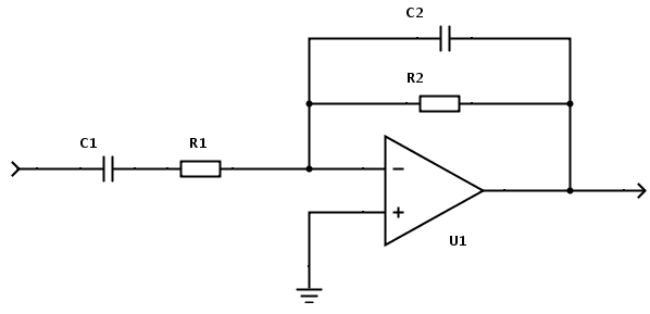
So lets start with the basic inverting buffer/gain stage. I think most are familiar with the circuit below, however note that the value of the resistors are some orders of magnitude lower than those you would see with VFB opamps. The opamp chosen for all these experiments is the Linear Technology LT1229 dual CFB opamp. That also seemed a good choice because the LTspice models should be good with this being an LT device.

How does this basic circuit simulate ? Well here is the result when supplied with a 50kHz squarewave. Not to bad on the face of it.

There is some slight ringing on the transistions as can be seen here.

At this point a couple of CFB specifics should be mentioned. Firstly, whereas a VFB design would use a small cap across Rf to tame any instability or to tailor the response, a CFB opamp must NEVER see capacitance added in that way. Secondly, the CFB opamp must NEVER drive a capacitive load directly but rather a small resistor should be added in series with the output to isolate the opamp from any capacitance.
Those are two golden rules. So lets see how simulation handles that with the following modifications to the circuit.

And here is the same squarewave test.

The result seems impressive. The cap has tamed the ringing (as it would in a VFB design) and yet adding a cap in this way is just not allowable with CFB. Simulation says otherwise though. So lets stop at this point and see what the reality is.
Well here is the actual basic design from the first picture. The actual opamp handling a 50kHz squarewave.

Initially it seems OK but is it ? A problem arises when the input is open circuit. In simulation there is nothing to see, the output hovers within a few femtovolts of zero. Open circuit the real version and its another story. Its unstable which is exactly how it should be and yet LTspice doesn't show a problem here.

And here is the reality of a 47pf cap (Cfb across Rf) being added. Total instability, again just as it should be. Yet again LTspice fails to simulate this most basic property of the CFB opamp. The scope setting was at 0.1 volts/div and the sweep speed 20nS (nano). That puts the instability at the 63mHz region.

So an interesting initial result. Using simulation it seemed "easy" to get a working amplifier but the reality was very different. There were other issues too. It was "unstabley unstable" under many conditions. The run of the PSU leads and test leads all played a part. Just me moving around the circuit changed it. DC offset was poor but variable, again that being a classic sign of instability. Surprisingly PSU decoupling played little part though. From none through to comprehensive, it made little difference, quite unbelievable when you realise this is a 100mHz bandwidth, 1000V/us chip. Scope probe capacitance is a real concern in measurement and adding any capacitance to the real opamp sends it crazy. In simulation (yet again) it doesn't.
So now we move on to making a real working and hopefully repeatable design. The basic configuration is OK but it needs refining. Firstly a 39 ohm "output" resistor is added to isolate the opamp from capacitive effects. This value is not a "fixed or optimum" value but just a guide depending on what the opamp drives. The inverting input sees the big change of having a resistor R1 added. This dramatically improves the stability and makes the design stable and repeatable. The value was determined experimentally. Below 33 ohm and it was marginal with some stability issues showing under certain conditions. 56 ohm and above and stability seemed fine and so 82 ohm was chosen as a "safe" value. So here is the final buffer/gain stage so far.

And here is the design for real. This shows a 200 kHz squarewave at 15 volts being applied. The top trace is the input and the bottom the output. The "invert" feature of the scope was used to correct the 180 degree phase inversion of the inverting configuration. DC offset was good in this final form to coming in at around 1.5mv. Power supply rejection ratio is something I didn't look at but what I did notice was the fact that the output trace visibly moved as I rapidly turned the power supply voltage up and down. So stabilised supplies are probably a must.

So that wraps up what is for me the just the first initial investigation into these very different and interesting opamps. Hopefully I will look at the non inverting gain stage next and see how that behaves in practice. One thing that was abundantly clear from all of this was "don't rely on simulation exclusively". Yes, its a fantastic tool but it has real limitations as well. Something to bear in mind when chasing that last zero or squiggle 😀
Until a few days ago I had never used a CFB opamp. This was also a great opportunity to put the designs into simulation and then take those on to develop real working "building blocks". I mention that point specifically, because ever more reliance is being placed on simulation and so seeing how simulation vs reality panned out would be interesting. The results were very suprising as you will see. I've also tried to keep this as practical as possible. As always, there are huge resources available from the manufacturers web sites and data sheets.
So lets start with the basic inverting buffer/gain stage. I think most are familiar with the circuit below, however note that the value of the resistors are some orders of magnitude lower than those you would see with VFB opamps. The opamp chosen for all these experiments is the Linear Technology LT1229 dual CFB opamp. That also seemed a good choice because the LTspice models should be good with this being an LT device.
How does this basic circuit simulate ? Well here is the result when supplied with a 50kHz squarewave. Not to bad on the face of it.
There is some slight ringing on the transistions as can be seen here.
At this point a couple of CFB specifics should be mentioned. Firstly, whereas a VFB design would use a small cap across Rf to tame any instability or to tailor the response, a CFB opamp must NEVER see capacitance added in that way. Secondly, the CFB opamp must NEVER drive a capacitive load directly but rather a small resistor should be added in series with the output to isolate the opamp from any capacitance.
Those are two golden rules. So lets see how simulation handles that with the following modifications to the circuit.
And here is the same squarewave test.
The result seems impressive. The cap has tamed the ringing (as it would in a VFB design) and yet adding a cap in this way is just not allowable with CFB. Simulation says otherwise though. So lets stop at this point and see what the reality is.
Well here is the actual basic design from the first picture. The actual opamp handling a 50kHz squarewave.
Initially it seems OK but is it ? A problem arises when the input is open circuit. In simulation there is nothing to see, the output hovers within a few femtovolts of zero. Open circuit the real version and its another story. Its unstable which is exactly how it should be and yet LTspice doesn't show a problem here.
And here is the reality of a 47pf cap (Cfb across Rf) being added. Total instability, again just as it should be. Yet again LTspice fails to simulate this most basic property of the CFB opamp. The scope setting was at 0.1 volts/div and the sweep speed 20nS (nano). That puts the instability at the 63mHz region.
So an interesting initial result. Using simulation it seemed "easy" to get a working amplifier but the reality was very different. There were other issues too. It was "unstabley unstable" under many conditions. The run of the PSU leads and test leads all played a part. Just me moving around the circuit changed it. DC offset was poor but variable, again that being a classic sign of instability. Surprisingly PSU decoupling played little part though. From none through to comprehensive, it made little difference, quite unbelievable when you realise this is a 100mHz bandwidth, 1000V/us chip. Scope probe capacitance is a real concern in measurement and adding any capacitance to the real opamp sends it crazy. In simulation (yet again) it doesn't.
So now we move on to making a real working and hopefully repeatable design. The basic configuration is OK but it needs refining. Firstly a 39 ohm "output" resistor is added to isolate the opamp from capacitive effects. This value is not a "fixed or optimum" value but just a guide depending on what the opamp drives. The inverting input sees the big change of having a resistor R1 added. This dramatically improves the stability and makes the design stable and repeatable. The value was determined experimentally. Below 33 ohm and it was marginal with some stability issues showing under certain conditions. 56 ohm and above and stability seemed fine and so 82 ohm was chosen as a "safe" value. So here is the final buffer/gain stage so far.
And here is the design for real. This shows a 200 kHz squarewave at 15 volts being applied. The top trace is the input and the bottom the output. The "invert" feature of the scope was used to correct the 180 degree phase inversion of the inverting configuration. DC offset was good in this final form to coming in at around 1.5mv. Power supply rejection ratio is something I didn't look at but what I did notice was the fact that the output trace visibly moved as I rapidly turned the power supply voltage up and down. So stabilised supplies are probably a must.
So that wraps up what is for me the just the first initial investigation into these very different and interesting opamps. Hopefully I will look at the non inverting gain stage next and see how that behaves in practice. One thing that was abundantly clear from all of this was "don't rely on simulation exclusively". Yes, its a fantastic tool but it has real limitations as well. Something to bear in mind when chasing that last zero or squiggle 😀
By inserting the 82 ohm resistor you lowered the gm and stabilized the loop. Nice technique!
Normally you cannot place a cap directly across the feedback resistor in a CFA amp without seeing the problems you noted.
Normally you cannot place a cap directly across the feedback resistor in a CFA amp without seeing the problems you noted.
Power supply rejection ratio is something I didn't look at but what I did notice was the fact that the output trace visibly moved as I rapidly turned the power supply voltage up and down. So stabilised supplies are probably a must.
Surely as you seem to be driving the op-amp to the rails, twiddling the PSU voltage will move the output trace?
Nice work, maybe you should alter your signature now 😉
Part 2. The non inverting configuration.
The diagram below shows the well known unity gain buffer with 100% feedback from output to inverting input. Lets see how this simulates both with and without R1 in circuit.

Here is the result of applying a 50kHz squarewave as an input signal.

And here is the ringing on the transitions.

And finally with R1 in circuit. Here we can see that R1 tames the HF response.

As before, lets take a look at reality. This shows the actual basic circuit as shown in the first picture. Here we can see two obvious problems that the simulation doesn't reveal. First there is obvious oscillation and instability and secondly, a substantial DC offset. The scope is on 0.5 volts/div and a 56 ohm "isolation" resistor was used on the opamp output to isolate the opamp from the probe capacitance. The oscillation was around 50mHz.

And here is with R1 present. This time the simulation and reality seem on the surface to agree. The buffer in this state seems stable, the hf has been tamed and the DC offset has reduced.

Its not perfect however. Lets remove the input and tie the opamp input to ground via the 100k and see how it simulates. This would be a typical unused input buffer on a preamp for example. It seems fine. The output trace is just random noise in the femtovolts region.


And here is the reality. Oscillation and a significant DC offset of around +20mv.

So we now have to try and develop the basic buffer into a usable building block. Lets look at both issues, the offset and the instability. Here is a slightly modified circuit set up in LTspice. A new resistor Rx has been added. Running the simulation with either R1 at 100k or R1 linked out give essentially the same result which is just a few femto volts of noise from the opamp. The DC offset is zero. A perfect simulation result.

The reality again is very different. With R1 at 100k the offset is around +10mv with a suspicion of HF oscillation. As R1 is reduced in value the DC offset falls and then swings negative as can be seen here. What was a suspicion of oscillation with R1 at 100k becomes more and more pronounced as R1 is reduced.

So we need to try and rehash the basic circuit to see what is going to work in practice. As you might have suspected, Rx is going to play a big part in this but thats not the whole story. The opamp non inverting input needs tying or referencing to zero volts under all conditions and so Rin has been fixed at 100k. In addition, a third resistor Rin has been added to prevent the non inverting input seeing effectively low or near zero impedance at AC. The DC offset seems compromised at all levels (relatively speaking... dc precision is not one of the CFB opamps fortes). So in practise, as the DC resistance seen by the noninverting input falls, the DC offset varies considerably. Around 33k was needed to null the output to zero (when Rx was 620 ohm). R1 and Rin as shown give a slight attenuation to the signal. Rin could easily be moved to the left side of R1.

Of course the next logical step is to take the buffer stage and turn it into a line stage with gain. Here is the initial starting point which in simulation seemed stable. In practice it was not as can be seen with a 20 volts pk/pk 1.6mHz oscillation appearing. I suspect this could be down to parasitics in the test set up because bringing a hand near the circuit stopped the oscillation.


Adding just 6pf from the noninverting input to ground cleaned the oscillation up but showed up another problem. Noise ! This was clearly visible on the scope with Rin at 100K. Of course such values are not consistent with the CFB opamp architecture and as Rin was reduced so the noise fell away. So this aspect of the CFB opamp needs far more work and looking into, particularly if use for audio line stages was envisaged. And finally, as with the inverting stage, the CFB opamp absolutely shines when it comes to bandwidth. This last picture shows the input (top) and output (bottom) at 1mHz and 20 volts pk/pk output. My generator doesn't have rapid rise/fall times but non the less the real world ability of the CFB opamp shows.

All in all, a very interesting exercise. Where it might lead I'm not sure. The CFB amp seems to have great potential. My worries on the CFB opamp are noise and power supply rejection. They are both things to look at in the future. Any audio amp using these opamps would be a radical departure from what we are familiar with but I suspect it could work well, possibly combining Vfb and Cfb each playing to their strengths.
The diagram below shows the well known unity gain buffer with 100% feedback from output to inverting input. Lets see how this simulates both with and without R1 in circuit.
Here is the result of applying a 50kHz squarewave as an input signal.
And here is the ringing on the transitions.
And finally with R1 in circuit. Here we can see that R1 tames the HF response.
As before, lets take a look at reality. This shows the actual basic circuit as shown in the first picture. Here we can see two obvious problems that the simulation doesn't reveal. First there is obvious oscillation and instability and secondly, a substantial DC offset. The scope is on 0.5 volts/div and a 56 ohm "isolation" resistor was used on the opamp output to isolate the opamp from the probe capacitance. The oscillation was around 50mHz.
And here is with R1 present. This time the simulation and reality seem on the surface to agree. The buffer in this state seems stable, the hf has been tamed and the DC offset has reduced.
Its not perfect however. Lets remove the input and tie the opamp input to ground via the 100k and see how it simulates. This would be a typical unused input buffer on a preamp for example. It seems fine. The output trace is just random noise in the femtovolts region.
And here is the reality. Oscillation and a significant DC offset of around +20mv.
So we now have to try and develop the basic buffer into a usable building block. Lets look at both issues, the offset and the instability. Here is a slightly modified circuit set up in LTspice. A new resistor Rx has been added. Running the simulation with either R1 at 100k or R1 linked out give essentially the same result which is just a few femto volts of noise from the opamp. The DC offset is zero. A perfect simulation result.
The reality again is very different. With R1 at 100k the offset is around +10mv with a suspicion of HF oscillation. As R1 is reduced in value the DC offset falls and then swings negative as can be seen here. What was a suspicion of oscillation with R1 at 100k becomes more and more pronounced as R1 is reduced.
So we need to try and rehash the basic circuit to see what is going to work in practice. As you might have suspected, Rx is going to play a big part in this but thats not the whole story. The opamp non inverting input needs tying or referencing to zero volts under all conditions and so Rin has been fixed at 100k. In addition, a third resistor Rin has been added to prevent the non inverting input seeing effectively low or near zero impedance at AC. The DC offset seems compromised at all levels (relatively speaking... dc precision is not one of the CFB opamps fortes). So in practise, as the DC resistance seen by the noninverting input falls, the DC offset varies considerably. Around 33k was needed to null the output to zero (when Rx was 620 ohm). R1 and Rin as shown give a slight attenuation to the signal. Rin could easily be moved to the left side of R1.
Of course the next logical step is to take the buffer stage and turn it into a line stage with gain. Here is the initial starting point which in simulation seemed stable. In practice it was not as can be seen with a 20 volts pk/pk 1.6mHz oscillation appearing. I suspect this could be down to parasitics in the test set up because bringing a hand near the circuit stopped the oscillation.
Adding just 6pf from the noninverting input to ground cleaned the oscillation up but showed up another problem. Noise ! This was clearly visible on the scope with Rin at 100K. Of course such values are not consistent with the CFB opamp architecture and as Rin was reduced so the noise fell away. So this aspect of the CFB opamp needs far more work and looking into, particularly if use for audio line stages was envisaged. And finally, as with the inverting stage, the CFB opamp absolutely shines when it comes to bandwidth. This last picture shows the input (top) and output (bottom) at 1mHz and 20 volts pk/pk output. My generator doesn't have rapid rise/fall times but non the less the real world ability of the CFB opamp shows.
All in all, a very interesting exercise. Where it might lead I'm not sure. The CFB amp seems to have great potential. My worries on the CFB opamp are noise and power supply rejection. They are both things to look at in the future. Any audio amp using these opamps would be a radical departure from what we are familiar with but I suspect it could work well, possibly combining Vfb and Cfb each playing to their strengths.
Surely as you seem to be driving the op-amp to the rails, twiddling the PSU voltage will move the output trace?
Nice work, maybe you should alter your signature now 😉
Thanks 🙂
The signature... I know I know. I'll get round to it some time 😀
I have just encountered a strange phenomenon. The test circuit was one dual opamp with one side connected as an inverting buffer and the other as a follower. Look closely at the picture and the trace and it shows or appears to show a very very slight roll off. The trace slopes. DC coupled throughout and no problem with the scope, well this can not be ! The output was four volts peak to peak at 10kHz.

To cut a long story short I finally scope'd the rails. The result is clear to see.

The scope is on 1 volt/div.
The power supply for this set up is a virtual ground generator consisting of a 741 and BC142/3 transistors with limiting at around 100 ma. The whole generator is actually an add on of mine to a Farnell 0-30 psu and the virtual ground is brought out to a spare unused socket on the front. There's no issue with the generator in the normal sense and the regulation is fine. In the many years I've used this and in all the work I have done with Vfb I have never encountered anything like this.
It seems the CFB opamps really need a very stiff supply. This is something that has really surprised me in practice. The ripple on the rail appears as soon as the opamp produces output, in other words even at the millivolt output level. Adding some 1000ufs fixed the problem but it makes you think 😀
To cut a long story short I finally scope'd the rails. The result is clear to see.
The scope is on 1 volt/div.
The power supply for this set up is a virtual ground generator consisting of a 741 and BC142/3 transistors with limiting at around 100 ma. The whole generator is actually an add on of mine to a Farnell 0-30 psu and the virtual ground is brought out to a spare unused socket on the front. There's no issue with the generator in the normal sense and the regulation is fine. In the many years I've used this and in all the work I have done with Vfb I have never encountered anything like this.
It seems the CFB opamps really need a very stiff supply. This is something that has really surprised me in practice. The ripple on the rail appears as soon as the opamp produces output, in other words even at the millivolt output level. Adding some 1000ufs fixed the problem but it makes you think 😀
Thats a good question, one I was wondering too. In practice I suspect not tbh. Reasons for saying that are that the rails (or rather the virtual earthg generator) had an easier time of it with just "one" individual opamp stage active. Also many of the earlier investigations looked at stability often with no signal applied and for that there was local HF decoupling.
Nice work Mooly! stability or oscillation problems using typical inverting/non inverting configurations are present only in CFB opamps? is there any problem when using a VFB opamp like opa2134 or ne5532 with typical inverting/non inverting gain configurations? for example :
If i want to use the classic passive RC bandbass filter used in amplifiers,before the inverting gain/buffer configuration on a CFB opamp LIKE LT1229 you tested will the extra components bring up oscillation problems?
If i want to use the classic passive RC bandbass filter used in amplifiers,before the inverting gain/buffer configuration on a CFB opamp LIKE LT1229 you tested will the extra components bring up oscillation problems?
An externally hosted image should be here but it was not working when we last tested it.
Last edited:
Thanks 🙂
For your first circuit, the inverting amp, there is no stability issue with normal vfb opamps. What you show is correct. The opamp should be chosen for one that is unity gain stable.
For the CFB opamp there is no problem adding a filter before the opamp section. Just remember to take account of the input impedance of the CFB depending on what mode you choose.
If i want to use the classic passive RC bandbass filter used in amplifiers,before the inverting gain/buffer configuration on a CFB opamp LIKE LT1229 you tested will the extra components bring up oscillation problems?
You might find this TI appnote of value for where you'd like to use a VFA-kind of circuit with a CFA. They've come up with a very nifty trick - a ferrite bead.
http://www.ti.com/lit/an/slyt081/slyt081.pdf
Last edited:
Nice work, maybe you should alter your signature now 😉
You were saying 😀
No doubt, current feedback amplifiers are more sensible to Power supply noise - regarding decoupling caps : any experiences for the placement of only one cap between the supply +/- rails nearby the chip, instead of using two caps from + and - to ground ? The interesting thing for this is possibly less noise on the ground rail. Or maybe doing both ?
Greetings, Philipp
Greetings, Philipp
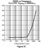
Here is the PSRR of the LME49713. It degrades over 10kHz.
A simple solution are 22 Ohm resistors in the supply feeds and 330uF caps to ground.
I usually decouple with one 0.1uF over the supply Pins.
Conventional decoupling works as well. At least in my builds i can not see a difference.
Never tried to compare it in terms of sound though so this should be done in the future.
Attachments
We dropped a CFB opamp into the ultimate opamp shootout and it did better than some. Post #226 and the circuit used just above.
http://www.diyaudio.com/forums/ever...tout-where-you-get-decide-12.html#post3701967
http://www.diyaudio.com/forums/ever...tout-where-you-get-decide-12.html#post3701967
- Status
- Not open for further replies.
- Home
- Source & Line
- Analog Line Level
- Current Feedback Opamps in simulation and practice.