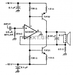
Hi all. Scheme published at seekic.com/circuit_diagram/Amplifier_Circuit without author's indication. It is a current amplifier and is not intended for common use in passive network systems: it can destroy components and speakers. Built one, it seems to respond well with NJM2608D (18V). With other opamps I can't do it because the power supply is the same as 18 VDC, very high. Would anyone know how to separate opamp rails from PNP-NPN power? The result looks good but, high volume distorts a lot. I already appreciate the opinions and advice. Thanks.
Attachments

An externally hosted image should be here but it was not working when we last tested it.
Усилитель мощности STONECOLD. Принципиальная схема, описание, чертеж платы.
Last edited:
Hi all. Scheme published at seekic.com/circuit_diagram/Amplifier_Circuit without author's indication. It is a current amplifier and is not intended for common use in passive network systems: it can destroy components and speakers. Built one, it seems to respond well with NJM2608D (18V). With other opamps I can't do it because the power supply is the same as 18 VDC, very high. Would anyone know how to separate opamp rails from PNP-NPN power? The result looks good but, high volume distorts a lot. I already appreciate the opinions and advice. Thanks.
Hi
this is super simple transconductance amp, you can get very high sq from it, if stable, depends on a speaker.
you can read more: Current drive for Loudspeakers
and my built example:
LM1875 transconductance amp
Your contributions are very valuable. A powerful concept: it transforms a modest solid state amplifier into a device with similar sound with thermionic valves. A warning for those who read too fast: do not use a passive network current amplifier for speakers. These devices are great for wideband speakers when are treated in the cabinet or still in multi-amplified systems, with active crossover. Thank you for your help.
Hey everyone. Does anyone know how to just decrease power to the opamp leaving more power for the output transistors?
The opamp only get very few power anyway
Some opamps use voltage less than 18v. To test others, I want to decrease it to 15 or 12VDC.
Like thisHey everyone. Does anyone know how to just decrease power to the opamp leaving more power for the output transistors?
Attachments
This only decreases the voltage, the current stays the same and the power you take from the power supply also stays the same.
As pointed out, the power the opamp needs is only a very small fraction from the total and not significant.
Jan
As pointed out, the power the opamp needs is only a very small fraction from the total and not significant.
Jan
We can't change the quiescent current of the op-amp. it is.But we can better coordinate the cascades with the OE
I have difficulties with the English language. I do not need to decrease the quiescent current: I need to lower the opamp supply voltage. In post # 1, NE5534 can connect with 20VDC but other opamps as NE5532 it can only 15 VDC. I need less tension but I don't have technical knowledge of how to do it.
So, when you said you want to lower power so that more power is available for the output stage. What you mean, is to lower the voltage for the opamp so you can have higher voltage for the output stage so more power.
That will work.
For lowering the voltage to the opamp you can use a cascode as shown before.
Jan
That will work.
For lowering the voltage to the opamp you can use a cascode as shown before.
Jan
Hey
The circuit in post-1 is NOT current feedback; rather, it is a transconductance amplifier producing a current output proportional to the voltage input. This is a voltage-controlled current source and distinctly NOT what you want to drive a speaker with.
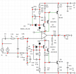
The circuit in post-2 is more likely what you want to build and is in fact a current-feedback amplifier. Circuits like this have been around since 1980 or earlier, and the post-4 circuit shows how to reduce the voltage on the opamp and/or increase the supply voltages to whatever you want. The only thing missing from post-4 is a means to control the idle current. The usual method is to add an adjustable current source from ground to one base-drive node. The opamp will adjust its current draw to make the other half of the circuit balance the side being set manually.
Speakers are tested from amplifiers that are close to being a voltage source. Since this is the standard, you will get the claimed performance from the speaker if you also use a voltage source to drive it - which thankfully is how every audio power amp is designed - except for oddballs.
The circuit in post-1 is NOT current feedback; rather, it is a transconductance amplifier producing a current output proportional to the voltage input. This is a voltage-controlled current source and distinctly NOT what you want to drive a speaker with.
The circuit in post-2 is more likely what you want to build and is in fact a current-feedback amplifier. Circuits like this have been around since 1980 or earlier, and the post-4 circuit shows how to reduce the voltage on the opamp and/or increase the supply voltages to whatever you want. The only thing missing from post-4 is a means to control the idle current. The usual method is to add an adjustable current source from ground to one base-drive node. The opamp will adjust its current draw to make the other half of the circuit balance the side being set manually.
Speakers are tested from amplifiers that are close to being a voltage source. Since this is the standard, you will get the claimed performance from the speaker if you also use a voltage source to drive it - which thankfully is how every audio power amp is designed - except for oddballs.
The current feedback term dates from 60 years ago and was used for a transconductance amplifier - the feedback was a sample representing the current.
It is only relatively recently that the chip bakers coined the CFA term. Hence the continuing confusion ;-)
Jan
It is only relatively recently that the chip bakers coined the CFA term. Hence the continuing confusion ;-)
Jan
Hey
The circuit in post-1 is NOT current feedback; rather, it is a transconductance amplifier producing a current output proportional to the voltage input. This is a voltage-controlled current source and distinctly NOT what you want to drive a speaker with..
If you go back to *this post* it sounds to me like a transconductance amplifier is what he originally intended:
Your contributions are very valuable. A powerful concept: it transforms a modest solid state amplifier into a device with similar sound with thermionic valves.
It will have some resemblance to a pure pentode valve amp with NO negative feedback. Gain will be directly proportional to impedance. You ordinarily would NOT want to drive a loudspeaker with it - but if the resulting sound is what floats your boat then there is nothing stopping you from doing it. If you did want to do some sort of solid state valve emulation, you would probably want to “compromise” the output impedance and make it non-infinite (the plate curves on a real valve have slope). The circuit is actually “too perfect” in theory, and will not sound as nice as a real pentode amp with no NFB. It will also have all the crossover distortion junk normally associated with solid state amps. Tubes cut on and off gracefully, transistors do not - their capacitances are highly nonlinear, and are at their worst right as they turn on and off.
As to why it sounded particularly bad - the output transistors do not have enough gain to drive the load. They might have a gain of 15 at an amp - woefully inadequate even for a 5532. You're current-clipping way early. You need darlingtons at a minimum on order to get it to work as “intended”. There also might be a stupid amount of crossover distortion.
We can't change the quiescent current of the op-amp. it is.But we can better coordinate the cascades with the OE
I was wrong there. We can reduce the current consumption of the opamp .In the above diagram ( post13 )The quiescent current of the op amp is reduced by a factor of 3 from 5.6 mA to 1.4 mA.
So we can change the opamp mode in this turn on
Last edited:
- Home
- Amplifiers
- Solid State
- Current feedback NE5532+TIP31/32