hello,
I like full symetric designs in power amps but I get bored with the double long tailed pair it demands, especially when wanting a JFET input, plus the two current sources that are needed, plus the four cascodes for isolating the FETs from the high voltage supply rails.
What kind of IC would you recommend as input stage for a power amplifier ?
Like many people, I started thinking about the OPA-134 : JFET input, qualified for audio, low noise, low offset. Is there an accurate OPA-134 Spice model I could use ? The Spice model needs to be accurate regarding the supplies input : how much current they sink in function of the current that's delivered by the output stage.
Then came the idea of getting a Current Mode amplifier as front-end. In the form of an IC. What kind IC would you advise ? Are there Current Mode amplifiers with a JFET non inverting input ?
See attached file. This is a Tina 7 Texas Instruments schematic, ready for simulation. Simulation results are not yet trustable, as the TL071 model is not accurate regarding the supplies inputs. The TL071 output is said to deliver 100mA while we still have moderate currents (like 2 mA) in the supplies ! This ruins the simulation.
Attachments

Here is a Tina 7 Texas Instruments schematic ready for simulation.
The front-end is a discrete version of a diamond buffer followed by a current-feedback amp. With this sub-optimal arrangement, the diamond buffer is open loop, not included into the feedback, so he adds its own distorsion.
One can see the viability of such approach when conduction a simulation.
-3dB bandwidth is more than 3 MHz
Slew-rate is about 300 v/µs
THD is 0.002%
All this with a VAS having less than 5mA quiescent current (Iq).
With a VAS Iq completely independent from the front-end Iq.
Because of the self-biased cascode arrangement used as VAS.
The reason why this design stands out is in the push-pull current mirror arrangement feeding the VAS. The current mirror arrangement can short circuit the VAS base for fast turn-off, and the current mirror arrangement can dump a high current into the VAS base, far more than twice the front-end quiescent current, for fast turn-on.
This is a kind of "Non Slewing Amplifier", however less complicated than Giovanni Stochino arrangements between 1995 and 1998 in Wireless-World (Electronics World).
Now that the concept got proven (on paper), please advise an IC that could be used as front-end, preferably a JFET input one.
Thanks
Attachments
That's the Alexander Current-Feedback Audio Power Amplifier. My design is somewhat different. It adds flexibility using a dedicated VAS.Google for "AN-211 analog devices".
The dedicated VAS is push-pull driven for fast slew-rates, relies on a self-biased cascode arrangement, boosts the open-loop voltage gain, and enables a VAS Iq that's completely independent of the front-end Iq.
Here is a Tina 7 Texas Instruments schematic ready for simulation.
The front-end is a discrete version of a diamond buffer followed by a current-feedback amp. With this sub-optimal arrangement, the diamond buffer is open loop, not included into the feedback, so he adds its own distorsion.
One can see the viability of such approach when conduction a simulation.
-3dB bandwidth is more than 3 MHz
Slew-rate is about 300 v/µs
THD is 0.002%
All this with a VAS having less than 5mA quiescent current (Iq).
With a VAS Iq completely independent from the front-end Iq.
Because of the self-biased cascode arrangement used as VAS.
The reason why this design stands out is in the push-pull current mirror arrangement feeding the VAS. The current mirror arrangement can short circuit the VAS base for fast turn-off, and the current mirror arrangement can dump a high current into the VAS base, far more than twice the front-end quiescent current, for fast turn-on.
This is a kind of "Non Slewing Amplifier", however less complicated than Giovanni Stochino arrangements between 1995 and 1998 in Wireless-World (Electronics World).
Now that the concept got proven (on paper), please advise an IC that could be used as front-end, preferably a JFET input one.
Thanks
I've used the AD844 in that position, it does accurately reflect the output current into the supply pins, but its not JFET input. And not specified specifically for audio, but that's just marketing of course...😉
jd
Thanks for your reply. The AD844 is indeed a kind of speed monster : 60 MHz bandwith (G=-1), 2000V/µs slew-rate (!), 150µV offset, Iq 6.5mA per amplifier. The input bias current is surprisingly low, only 200nA. But it means a voltage of 2mV into a 10K resistor. That's too much for a ICL (input capacitorless) arrangement. A resistance of 10K resistor is, as an example, the 100K volume pot at -20dB. The voltage variation should be less than 0.1mV, which commands an input bias current smaller than 10nA.I've used the AD844 in that position, it does accurately reflect the output current into the supply pins, but its not JFET input.
I really would like to try a JFET front-end.
Maybe the AD8033 (single amplifier) or AD8034 (dual amplifier) FET op-amp ?
AD8033 | Very Low-Cost High-Speed FastFET? Op Amps | Operational Amplifiers (Op Amps) | Amplifiers and Comparators | Analog Devices
The AD8033 looks more than decent, with 80 MHz bandwith (G=+1), 80V/µs slew-rate, 1mV offset, Iq 3.3mA per amplifier.
The well known OPA-134 FET op-amp looks slow, with 8 MHz bandwith (G=+1), 20V/µs slew-rate, 1mV offset, Iq 4.0mA per amplifier.
Precision Amplifier - Wide Bandwidth - OPA134 - TI.com
Do you see any other mainsteam JFET IC that could be used as front-end ?
Here is a Tina 7 Texas Instruments schematic ready for simulation.
The front-end is a discrete version of a current-feedback amp.
It is an inverting amp.
The input impedance is 1K, quite low. This is the price to pay for dropping the input diamond buffer (see preview version).
The front-end is a discrete version of a current-feedback amp.
It is an inverting amp.
The input impedance is 1K, quite low. This is the price to pay for dropping the input diamond buffer (see preview version).
Attachments
attached you will find two simplified versions. If one can drive a 1K ohm impedance, there is no need for an IC font-end. Four discrete transistors wired as a feedback diamond buffer can do the job. Performance is amazing (on simulation).
Attachments
A similar topology is used by ARCAM in some of their amplifiers, usually with a TL072 as the frontend. They use one half as a V to I stage, and the other as a servo.
Unfortunately if one tries to embed a conventional op-amp, it all gets unstable.
At first glance, the attached Tina 7 Texas Instruments simulation file works fine :
- Analysis / DC Analysis / Table of DC results : everything okay
- Analysis / AC Analysis / AC Transfer Characteristic : very nice bandwith
With a 0,5V sinus input at 1 KHz, the Fourier Analysis of VOUT gives about 0,003% distorsion. Quite decent, isn't ?
However, with a 0.5V squarewave input at 10 KHz, the simulations delivers an oscillation.
I have tried different things, for getting more useful results, but no luck.
Any help appreciated.
Attachments
Last edited:
Finally I managed to embed a conventional op-amp, and get it stable.
See attached Tina 7 Texas Instruments simulation file : it is working fine.
But the frequency compensation is ugly, and not possible using one IC. We don't have access to the terminals where the frequency compensation gets applied.
With a 0,5V sinus input at 1 KHz, the Fourier Analysis of VOUT gives about 0,028% distorsion. This is 10x worse than without the frequency compensation scheme.
We better don't use a OPA-134 in such topology.
The true current feedback approach arrangement seems to be more efficient.
It is amazing to see the level of performance delivered by a few discrete (well matched and thermally coupled) transistors.
Next try will be using a AD8033 IC as front-end. It is not a current-feedback device, but it is much faster than the OPA-134.
How to simulate an Analog Devices AD8033 FastFET Op Amp with 80 Mhz bandwith and 80V/µs slew rate ? What topology ?
I should run a test of my OPA-134 implementation alone. Maybe my simulated OPA-134 already has the speed of the AD8033. This would mean that using an IC as front-end is a dead end.
Any suggestion welcome.
Attachments
Using LME49860
Hi, Just stumbled across your thread while looking for people who would like to build an input buffer stage using discrete. I have a nice little buffer amp I designed, but maybe a different thread would be better.
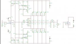
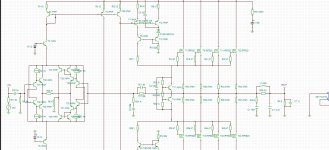
In any case: I took a peek at where your going on your current design process, and offer this example of a clean way to do an IC front end, using current feedback in the main amplifier.
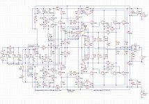
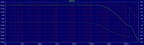
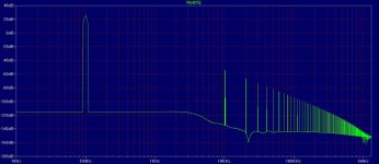
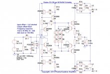
The first image is the schematic proper. The second image details small signal bandwidth and phase. And the third image is an FFT of distortion at 100hertz.
This is a nice clean topology, and is amendable to the OPA134, or OPA627, with small changes in compensation.
Enjoy!
Paul Vonharnish
Phoenix/Cauldron amplifiers
Hi, Just stumbled across your thread while looking for people who would like to build an input buffer stage using discrete. I have a nice little buffer amp I designed, but maybe a different thread would be better.
In any case: I took a peek at where your going on your current design process, and offer this example of a clean way to do an IC front end, using current feedback in the main amplifier.
The first image is the schematic proper. The second image details small signal bandwidth and phase. And the third image is an FFT of distortion at 100hertz.
This is a nice clean topology, and is amendable to the OPA134, or OPA627, with small changes in compensation.
Enjoy!
Paul Vonharnish
Phoenix/Cauldron amplifiers
Attachments
Hello, thanks for your reply. At first glance, it looks more elaborate than the Kuroda 1982 amplifier. See here http://www.diyaudio.com/forums/solid-state/164476-kuroda-tl071-60w-fet-amp-1982-a.htmlThis is a nice clean topology, and is amendable to the OPA134, or OPA627, with small changes in compensation.
I'm not talking about the output stage, but about the way the opamp gets interfaced with the VAS. Did you know about the Kuroda 1982 amp upon designing yours ? Did you know about the Alexander amp ? If yes/yes, can you describe the features of your implementation ? Thanks. Steph.
If you read th e Alexander amp app note mentioned earlier, you will see that if you return the compensation cap, which in a conventional CFA goes from the VAS output to GND, back to the feedback summing junction, you get quite an improvement in phase margin.
However, looking quickly at your first cct diagram in your initial post, this looks like a voltage feeback topology. CFA will look a lot different. Take another look athe Alexander amp and how the feedback is configured - this should help point you in the right direction.
However, looking quickly at your first cct diagram in your initial post, this looks like a voltage feeback topology. CFA will look a lot different. Take another look athe Alexander amp and how the feedback is configured - this should help point you in the right direction.
Last edited:
About Kuroda amplifier
Hi Steph,
In answer to my knowledge regarding the amplifier topologies you mention: No, and no. ;-) At first blush, nether amplifier would appear to be very desirable in an audio application. I see lots of probability for ringing and overshoot, and generally don't care to use FET's, unless they are included in an actual IC. Fet matching is always a serious problem in discrete design, and frankly, I don't care for the sonics either.
The amplifier I published is my own take on the Harman Kardon Citation 16 of yore. (Circa 1976) The input to the VAS section is primarily through Q5 and Q6, which are biased by cascode current sources. A person could go with some simpler compound current sources, but I prefer the cascode treatment.
The VAS gain in my example is controlled primarily by R26, R27, R28, R29, and compensation is augmented by C13, C14.
I also see potential power supply rejection issues in the examples you mentioned, whilst the topology I posted yields supply rejection figures in the
-180db range.
Also, I believe a person could drive an IC section with a simple input buffer, (somewhat like the example I will post here) but feedback in closed loop mode, would need further attention.
Enjoy!
Paul Vonharnish
Phoenix/Cauldron Amplifiers
Attachments
- Status
- Not open for further replies.
- Home
- Amplifiers
- Solid State
- Current Feedback IC input in a power amp