There've been some ideas about DIY MOSFET (and other gain device) matching. Nelson Pass has written a couple of articles:
http://www.firstwatt.com/pdf/art_matching.pdf
http://www.firstwatt.com/pdf/art_mos_test.pdf
The second of these pieces goes well beyond the goals of this project. The circuits from the first are quick for measurements such as: "for each of these MOSFETs what's the drain current for a specified gate source voltage?", but slower for measurements such as: "for each of these MOSFETs what's the gate source voltage for a specified drain current?" Since in the latter case for every MOSFET in turn a pot must be adjusted until a meter reads the desired current before the gate source voltage can be measured, while in the former case the pot can be set once for all the MOSFETs.
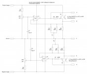
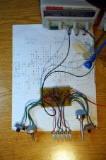
I designed this circuit so that when a MOSFET (or JFET or bipolar) is plugged in, an attached multimeter automatically reads the gate source voltage required for a previously set drain current. In particular, the pot adjusting the drain (or emitter) current is only set once, at the start of measuring a whole batch of MOSFETs.
Ther're no special requirements for the opamps, TL071 symbols just happened to be handy when I drew the circuit. When I built it I used a TL072, and many other general purpose opamps will also work.
The upper half of the circuit (with test device Q1) is for N-channel FETs and NPNs, and the lower half (with Q2) is for P-channel FETs and PNPs. Both halves work the same way. The opamp's configured as a follower. By negative feedback it adjusts the voltage at the test device's gate or base to be such that the voltage at its source or emitter is the same as the voltage at the opamp's non-inverting input, which is set by the pot. Since this voltage is also the voltage across the load resistors (R3, R6 & R9 or R4, R8 & R10) the setting of the pot also determines the source or emitter current of the device being measured.
The switches allow the load resistance to be reduced so that high drain or emitter currents can be used without the load resistors' overheating. Also the circuit can be run from bench supplies, so that the rail voltages can be adjusted to keep power dissipation under control in the device being measured.
For N-channel FETs or NPNs measure the voltage from point A to point B to get Vgs or Vbe. The voltage across the load resistor can be measured form point B to point C. It's (of course) related to the drain or emitter current by ohm's law and the value of the load resistance. So to have the most accurate knowledge of drain/emitter current, measure the load resistance first.
Similarly for P-channel FETs or PNPs the voltage from point D to point E is Vgs or Vbe, and the voltage from point C to point D is the voltage across the load resistance, etc.
http://www.firstwatt.com/pdf/art_matching.pdf
http://www.firstwatt.com/pdf/art_mos_test.pdf
The second of these pieces goes well beyond the goals of this project. The circuits from the first are quick for measurements such as: "for each of these MOSFETs what's the drain current for a specified gate source voltage?", but slower for measurements such as: "for each of these MOSFETs what's the gate source voltage for a specified drain current?" Since in the latter case for every MOSFET in turn a pot must be adjusted until a meter reads the desired current before the gate source voltage can be measured, while in the former case the pot can be set once for all the MOSFETs.
I designed this circuit so that when a MOSFET (or JFET or bipolar) is plugged in, an attached multimeter automatically reads the gate source voltage required for a previously set drain current. In particular, the pot adjusting the drain (or emitter) current is only set once, at the start of measuring a whole batch of MOSFETs.
Ther're no special requirements for the opamps, TL071 symbols just happened to be handy when I drew the circuit. When I built it I used a TL072, and many other general purpose opamps will also work.
The upper half of the circuit (with test device Q1) is for N-channel FETs and NPNs, and the lower half (with Q2) is for P-channel FETs and PNPs. Both halves work the same way. The opamp's configured as a follower. By negative feedback it adjusts the voltage at the test device's gate or base to be such that the voltage at its source or emitter is the same as the voltage at the opamp's non-inverting input, which is set by the pot. Since this voltage is also the voltage across the load resistors (R3, R6 & R9 or R4, R8 & R10) the setting of the pot also determines the source or emitter current of the device being measured.
The switches allow the load resistance to be reduced so that high drain or emitter currents can be used without the load resistors' overheating. Also the circuit can be run from bench supplies, so that the rail voltages can be adjusted to keep power dissipation under control in the device being measured.
For N-channel FETs or NPNs measure the voltage from point A to point B to get Vgs or Vbe. The voltage across the load resistor can be measured form point B to point C. It's (of course) related to the drain or emitter current by ohm's law and the value of the load resistance. So to have the most accurate knowledge of drain/emitter current, measure the load resistance first.
Similarly for P-channel FETs or PNPs the voltage from point D to point E is Vgs or Vbe, and the voltage from point C to point D is the voltage across the load resistance, etc.