In post #1, I forgot to list the Impasse Preamplifier http://www.diyaudio.com/forums/pass-labs/136835-impasse-preamplifier.html as a suitable F4 gain stage. I have built the Impasse and it sounds very good.
Thanks ZM. Is there a way to move the schematics from post #10 to posts #1 and #2 respectively?you can edit #1
... I need do look more carefully at the end-to-end square wave response to see if your use of an RC snubber might be useful.
I doubt it - I used it as a precaution because my prototypes were very messy, but nevertheless stable...
Thanks ZM. Is there a way to move the schematics from post #10 to posts #1 and #2 respectively?
you can put whatever you want in #1 , but for later ones - just use report button in particular post
that way Mods will read it , eventually
I could be missing it, but these seems little difference between the Curly and the LSK preamp. For the less well versed of us, can someone point out what the real differences are?
The topology is identical (without the output buffer). The difference is only in the choice of operating voltages, currents, and resistor selection. What I am reporting is the actual integration into an F4 and its end-to-end performance.I could be missing it, but these seems little difference between the Curly and the LSK preamp. For the less well versed of us, can someone point out what the real differences are?
... actual integration into an F4 and its end-to-end performance.
And you did great. Preamp like this is what the F4 is actually made for. It's easy to get higher voltage rails (needed for the preamp) from F4's transformer so the integration is easy and straightforward and the basic idea (high linearity, no feedback loop) is well preserved. Well done !
Thanks for the complements. 🙂 Are proposing a voltage doubler using the F4 transformer? I hadn't considered that, but given that less than 50mA is required from each higher voltage rail, that should be easy. I just used a Hammond 229B88 transformer which has a pair of 44V secondaries.\ ... It's easy to get higher voltage rails (needed for the preamp) from F4's transformer so the integration is easy and straightforward ... !
In a way - I use this routinely (PSU sch. from post #1), works better than other "voltage doubling" schemes....Are proposing a voltage doubler using the F4 transformer? ...
IME, LM317/337 are producing a certain amount of HF noise at the output, but in this specific case we have an advantage - the preamp has the constant current draw from the PSU so we can add nice RC elements at the regulators' +/- outputs (10R + 100uF) to filter that noise out. Sometimes, the difference made by this filter can be even heard... 😉
Would you put that filter at the folded cascode "load" resistor or at the PS? Seems to me that there would be a noise advantage placing it at the cascode.IME, LM317/337 are producing a certain amount of HF noise at the output, but in this specific case we have an advantage - the preamp has the constant current draw from the PSU so we can add nice RC elements at the regulators' +/- outputs (10R + 100uF) to filter that noise out. Sometimes, the difference made by this filter can be even heard... 😉
At the PS +/- outputs - we want clean PS voltage.Would you put that filter at the folded cascode "load" resistor or at the PS? Seems to me that there would be a noise advantage placing it at the cascode.
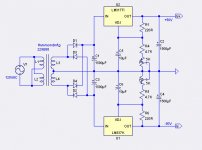
Your circuit uses cap. multiplier filters for the 51V supplies, but does no regulation and has significantly higher ripple than from the TL431. It can be argued that regulation is not needed for the folded cascode IF both +51 and -51 supply voltages vary (nearly) identically with mains and power transformer load variations, since the resulting current variations will cancel. Otherwise the cascode output voltage offset will vary. Since I am NOT using a capacitor between the cascode output and the F4 input, I was concerned about the output offset and after some analysis concluded it was not a problem for offsets up to 0.1V-0.2V or so, since JFET follower input stage has a floating output and cap. coupled to the output MOSFET gates.In a way - I use this routinely (PSU sch. from post #1), works better than other "voltage doubling" schemes.
However, if you managed to wade thru the Blowtorch threads, you will have noticed that John Curl went to extremes on his power supply design. Sme of that might have been related to the RIAA phono input he was designing for, but it was probably major overkill.
So far, I cannot detect any audible noise problems listening to my Curly-F4.
In the previous post I forgot to mention that the power supply noise issue is greatly reduced since the signal levels are 20dB above normal line levels.
I've shown the PSU circuit just as an example of easy integration with F4 by using the same transformer.
By changing a few values it can be optimized for very low ripple/noise...
By changing a few values it can be optimized for very low ripple/noise...
How about this variant "voltage doubler"? This uses a topology that avoids DC in the transformer windings, which would probably not a problem for the F4, and it used in many of the FirstWatt power supplies. It is shown here using the TL431, but could just as easily use your cap. multiplier.
How about this variant "voltage doubler"? This uses a topology that avoids DC in the transformer windings, which would probably not a problem for the F4, and it used in many of the FirstWatt power supplies. It is shown here using the TL431, but could just as easily use your cap. multiplier.
It seems that you forgot to attach schematic/link ?
- Status
- Not open for further replies.
- Home
- Amplifiers
- Pass Labs
- Curly-F4