Do you still have negative voltage on the output of the TL072? With the resistor, I'd expect 0v.
Do you have any solder bridges on the output pads?
All of the outputs out of the circuit?
Do you have any solder bridges on the output pads?
All of the outputs out of the circuit?
That should be enough to drive the LM211 to produce ±5v output.
If you want more out of the TL072, you can reduce the resistance of the 100k series resistor. You may be able to go as low as 10k. Too low may drive too much signal into the TL072 and make it act strangely.
If you want more out of the TL072, you can reduce the resistance of the 100k series resistor. You may be able to go as low as 10k. Too low may drive too much signal into the TL072 and make it act strangely.
Do you have the 1000pf cap across the gate and source?
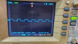
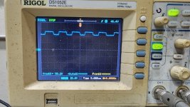
Is the LM211 swinging ±5v?
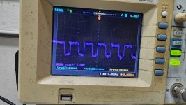
The waveform should be a fixed square wave. If you're driving signal into the amp, remove the signal from the RCA input.
Is the LM211 swinging ±5v?
The waveform should be a fixed square wave. If you're driving signal into the amp, remove the signal from the RCA input.
Is the waveform that you posted for the gate accurate? It should be the same signal as you have on the LM211 but shifted up to the rail.
Do you have a different waveform on the negative drive (move the cap or install one there.
Are you taking the signal from the leg of the 1000pf capacitor?
Do you have a different waveform on the negative drive (move the cap or install one there.
Are you taking the signal from the leg of the 1000pf capacitor?
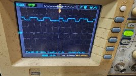
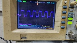
Yes I am taking the signal from the 1000pf leg attached to gate.
I installed another 1000pf on 640n side.
On 9640 gate the signal oscillates above positive rail. And on 640n side it oscillates below negative rail.
I installed another 1000pf on 640n side.
On 9640 gate the signal oscillates above positive rail. And on 640n side it oscillates below negative rail.
Are you looking at the rail and signal at the same time?
Do you know how to use your scope in differential mode?
Do you know how to use your scope in differential mode?
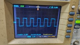
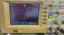
5v/div, DC coupling, ch2 on the source leg. Ch1 on the gate leg. << for FET location with the 1000pf cap.
There is too much noise to tell much.
I don't see how it's showing that you are driving above or below the rails. Don't you read 0 ohms between the collectors of the driver transistors (Q6 and Q9) on the driver board and the rail (source leg of outputs).
Do you have another scope?
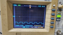
If you ground the scope to the negative speaker terminal and probe the output source legs (normal mode, 20v/div), do you see a clean straight trace?
Do you get a clean straight trace if you touch the probe to the negative speaker terminal when the scope is grounded to that terminal?
I don't see how it's showing that you are driving above or below the rails. Don't you read 0 ohms between the collectors of the driver transistors (Q6 and Q9) on the driver board and the rail (source leg of outputs).
Do you have another scope?
If you ground the scope to the negative speaker terminal and probe the output source legs (normal mode, 20v/div), do you see a clean straight trace?
Do you get a clean straight trace if you touch the probe to the negative speaker terminal when the scope is grounded to that terminal?
Yes I am seeing zero ohms between collectors of driver transistor to the source of outputs.
I don't have another scope.
Yes the source line is straight and also the negative terminal is also straight.
I don't have another scope.
Yes the source line is straight and also the negative terminal is also straight.
Do you get a clean signal/trace if you go back to the differential mode settings and probe the gate/source for the PS FETs?
- Home
- General Interest
- Car Audio
- CT Sounds AT900-1D