I want to reduce the output volume gain, which options should I changeThe Volume was so loud that at 30% of my the volume bar, my whole table vibrate
What hardware are you using? Which amp is used?I want to reduce the output volume gain, which options should I change
IIRC equalizer has some kind of master gain, so you may change it.

I'm using the qcc3031 module (it has its own amplifier tpa6132a2) and tpa3110 as my loudspeaker amplifierWhat hardware are you using? Which amp is used?
In addition, there is an odd issue with the same equalizer setting in my image where, in some songs like Misery by Maroon 5 and Anna Sun by Walk the Moon, and Pompei by Bastile, the background vocal and instruments were louder and clearer than the voice of the singer.
According to datasheet, you can set gain using pins GAIN0 and GAIN1. Probably your speakers do not need a lot of power to sound loud.tpa3110
I don't see any problem with keeping volume level below 30%
Then change equalizer settings to make it better. That's really subjective, so only real advice is to adjust the parameters of EQ according to your own preference.the background vocal and instruments were louder and clearer than the voice of the singer.
This should be possible, but you will have to write some code for that. If your oled display is i2c, see how to add i2c. You probably can control the ws2821b in a similar manner, but because it's not i2c nor spi, you'll have to use bit-banging technique.can I reprogram my qcc3031 module to control a small OLED display, a relay, or the ws2821b led in the same way that an Arduino can?
Many thanks. Can I send a string or other data from my phone and manage it on the QC3031, too?This should be possible, but you will have to write some code for that
and also I want to get the byte data of the audio output too, should there be a problem , thank you a lotMany thanks. Can I send a string or other data from my phone and manage it on the QC3031, too?
Yes. But again, more code. Either use GAIA or create your own BLE service. No instructions exist, but you can research how it's done in firmware itself. Strongly recommend using something like QCC5144 (BTM544 should be pin-to-pin compatible with BTM331) or QCC5171(BTM571 will require new PCB).Many thanks. Can I send a string or other data from my phone and manage it on the QC3031, too?
Do you want to make a light show or spectrum analyzer? I don't see an easy way to do that, but probably you want DSP program which will act as a passthrough and will somehow process audio samples to extract spectrum values? This is possible, but no ideas how you would transfer that data from DSP back to application core. There are some IPC mechanisms, but I'm not sure which one of them would be the best. Messages look too complex. Probably reading data from source directly will work, but don't ask me how to do that.and also I want to get the byte data of the audio output too, should there be a problem , thank you a lot
This is definitely not possible on QCC3031, you will need QCC5 series chip to do that. I would recommend QCC5171 as it's twice the performance compared to QCC5144.
maybe using another processor here to create the light show would be easier. Maybe the Attiny85 would be best in my case. Then I have to use the Qcc3031 as a Bluetooth serial to send the data on my phone to the attiny85 through serial or i2c. So GAIA will properly work in this case, right?you want DSP program which will act as a passthrough and will somehow process audio samples to extract spectrum values?
and GAIA Document would help me a lot. Thank
can you explain why using the Qcc5144 would be better?QCC5144
Thank you a lot for answering all of my question
Last edited:
Are you sure Attiny85 has enough performance? QCC5171 definitely has, also it has FFT library included, so it's not that hard to implement the DSP code itself. It will have 2 inputs (stereo audio) and 3 outputs (stereo audio + spectrum data). As always, the interaction is the hardest part. You'll have to modify some code for application core, but I thing that using SinkMap (firmware will take care about audio and you will only need to send this data to LEDs). Maybe it's a wise idea to still use Attiny, but just for periphery: OLED and WS2812B. This way QCC5171/44 will do all the heavy lifting and Attiny will just receive data via UART (see this or this).maybe using another processor here to create the light show would be easier. Maybe the Attiny85 would be best in my case.
It depends. You will have to right code for QCC either way, but if you'd go with BLE approach, you won't have to write a lot of code for your smartphone. If you'll implement BLE Nordic UART Service (NUS), you would be able to use already existing ecosystem of apps which support it.Then I have to use the Qcc3031 as a Bluetooth serial to send the data on my phone to the attiny85 through serial or i2c. So GAIA will properly work in this case, right?
GAIA, on the other hand, is different for QCC3031 and QCC5144/71, and QCC3031 GAIA app is available in source code form only for Android. It's also quite old at ~4 years, so it would be hard to implement. BLE NUS will be very similar between QCC5144/71 and QCC3031, so in case you will switch to them later, it would be pretty easy to port the code.
80-CF422-1.pdfand GAIA Document would help me a lot.
Programmable DSP (so LDAC or LC3plus HR possible), better software architecture. QCC5171 is dual-core @240MHz, while QCC5144 is only 120Mhz. Given (almost) the same price, QCC5171 is better (at 14$ it's actually little bit cheaper than QCC5144 at 15$, no ideas why tho).can you explain why using the Qcc5144 would be better?
So I would recommend using BLE, DSP for processing the audio and separate MCU for controlling the periphery via UART. You can certainly get rid of the separate MCU, but it will be a bit harder to code. Or you can get rid of the DSP code and use something like Raspberry Pi Pico (5$) for light effects (it also has ADC, so you can connect it to line out of the QCC)
I can help you with such a project, send me a PM with your GitHub account name and I will add you to private repo with QCC5171 (or QCC5144. They're almost the same) firmware (stock). You'll have to write most of the code by yourself, but I will help you in case of problems.
Last edited:
This sounds thrilling. That feature will make it easier for me to complete my project. Perhaps I'll order the QCC5171 to put this to the test.QCC5171 definitely has, also it has FFT library included, so it's not that hard to implement the DSP code itself. It will have 2 inputs (stereo audio) and 3 outputs (stereo audio + spectrum data).
My previous concept was quite simple. I plan to connect the Qcc3031 audio output to another MCU (attiny 85 with fix fft or The pico like your suggestion). The MCU will then take care of the rest. However, with the spectrum data output, the MCU does not have to do all of the heavy liftings, and it may even be possible to eliminate an extra MCU here As you said. Getting rid of an extra MCU will leave me with more space on the PCB.
So, how exactly do I port the NUS Code to the QCC3031, and wherein the source do I make the necessary changes to allow this fantastic feature?but if you'd go with BLE approach, you won't have to write a lot of code for your smartphone. If you'll implement BLE Nordic UART Service (NUS),
I can help you with such a project, send me a PM with your GitHub account name and I will add you to private repo with QCC5171 (or QCC5144. They're almost the same) firmware (stock). You'll have to write most of the code by yourself, but I will help you in case of problems.
Thank you so much :>>> , I will send you my github username right away, man, it's always nice to work with someone who has more experience than you.
Once again thank you alot for answering all my question and point me to a better direction.
The example of the BLE service is located at apps/libs/gatt_ama_server/ (In QCC5171's firmware source it is at adk/src/libs/gatt_ama_server/), so you'll need to look into the code and see how it's implemented. There are also other services, such as BLE HID (it is also available on nRF SoCs, so you can look into how it is implemented). Original NUS code is available for nRF52/53, so you can look how it's done there. Some general BLE knowledge would certainly help a lot, so read something about it.So, how exactly do I port the NUS Code to the QCC3031, and wherein the source do I make the necessary changes to allow this fantastic feature?
I'd say it would be easier to do it in two steps: initially using external MCU and then getting rid of it. This will certainly make your life easier while debugging.Getting rid of an extra MCU will leave me with more space on the PCB.
So this will handle the Data I send from my phone and if I want to pass this from the qcc to my external MCU through serial, which file should also need to change. i can't seem to find the folder that control serial in the source code that you providedThe example of the BLE service is located at apps/libs/gatt_ama_server/
Last edited:
If you want to use UART, you'll have to create new C source files, refer to 52bluetooth articles from one of the previous posts.So this will handle the Data I send from my phone and if I want to pass this from the qcc to my external MCU through serial, which file should also need to change. i can't seem to find the folder that control serial in the source code that you provided
So you will need to create directory for BLE service (based on existing examples) and files for UART (based on articles). Then BLE will call function which will write data to UART. Or other way round in case you'll need to send some data back to phone.
Thank you so much for the extra info and packages. Digging on that.That's because it doesn't exists. Apparently, the distribution model has changed: ADK Toolkit and firmware source code are separate things now.
You can find firmware source code (adk-src-1-0_qtil_standard_oem.7z) at the same link. There's also qcc5151 headset source firmware (qcc5151_headset_test_r00285.part*.rar). You'll need to open corresponding x2w file in MDE and compile it. By default TWS requires modules to have their BT address differ by one, so you'll need two different XUV files for each module.
Afaik you'll have to build firmware from source. IIRC that's subsys7_config5.htf and subsys1_config2.htf files.
This tool is for older QCC512x/302x/303x. In newer QCC5151 you can refer to earbud_ui_config.c and *.buttonxml files for setting up PIO.
I would suggest you to spend some time just looking into different files so that you'll know what's where.
PDF documents will also help you a little bitaddons/ - various addons (e.g. Google Assistant.)
adk/ - various libraries: A2DP implementation, BLE GATT servers and clients, buttons, ...;
audio/ - code for audio DSP (equalizer, audio decoders/encoders, ...)
bluetooth/ - patches and description of tuning keys for the Bluetooth subsystem
earbud/, example_apps/, headset/, source_apps/ - various projects
os/ - operating system + code for interaction with it
rdp/ - case firmware for TWS earbuds (STM32)
system/ - patches and description of tuning keys for OS (presumably)
tools/ - various utilities (simulator, debugger)
I was porting LDAC to QCC5125. It works fine with my phone (1+ 7 Pro), but apparently some other phones do have problems.
I heard about Galaxy Note 9 and Huawei Mate 30, probably others too. Unfortunately, no way to test them, so I need help from someone with access to smartphone with LDAC support and QCC5125-based device (please make sure to backup your stock firmware before flashing mine). It will restart if fails. Other way to see that it failed is to connect via MDE 2.3 debugger and look at statuses of cores. They all should be "Halted".
This is what I got as instructions for reproducing the error:
If firmware fails, please contact me via PM.1. When the phone LDAC is on, link QCC5125, then turn the phone LDAC off, then play music normally.
After stop playing music, turn LDAC on, which is normal, and then play music, sometimes there will be problems.
2. When the phone LDAC is off, link QCC5125, then turn on LDAC switch, this time is normal, then play music, the
QCC5125 will restart, Bluetooth disconnected, this will occur every time
Attachments
I'm tracking down random failures of the BTM331, and so far have obtained BlueSuite 3.3.10, unlocked the chip, and created a .xuv Dump of original firmware using NvsApp. Is the .xuv file a valid backup?
I've tried HidDfuApp without success (maybe a DFU dump is preferred?). I see PIDs 0x4000 and 0x4007. The DFU app will only connect to 0x4007, then returns an error.
I've tried HidDfuApp without success (maybe a DFU dump is preferred?). I see PIDs 0x4000 and 0x4007. The DFU app will only connect to 0x4007, then returns an error.
Attachments
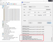
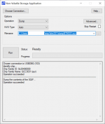
It should be. You can look into it (as text file), it is similar to Intel HEX concept. The format is the following: @ADDRESS VALUEI'm tracking down random failures of the BTM331, and so far have obtained BlueSuite 3.3.10, unlocked the chip, and created a .xuv Dump of original firmware using NvsApp. Is the .xuv file a valid backup?
Empty file would only show you "FF"s (hexadecimal). If the firmware doesn't have much custom-developed code, you may compile your own version of firmware, see few last pages for instructions. In case of failure you may just use debugger (available as a part of MDE, for QCC3031 you'll need ADK 6.4 and MDE 2.3)
HidDfuApp is useless unless you're a developer.I've tried HidDfuApp without success (maybe a DFU dump is preferred?). I see PIDs 0x4000 and 0x4007. The DFU app will only connect to 0x4007, then returns an error.
Thanks, @o11111! The .xuv dump is 57Mb and seems valid. I'm still trying to obtain access to appropriate versions of MDE and ADK from Qualcomm...
I've had multiple BTM331s fail to boot after several days of use, despite clean soldering and a well regulated 3v3 supply. Transplanting the 25U6435F flash memory chip from a new BTM331 to a failed BTM331 resolves, so the QCC3031 is not to blame. Maybe QSPI corruption at boot? Hopefully a re-flash helps next time the bug appears.
I've had multiple BTM331s fail to boot after several days of use, despite clean soldering and a well regulated 3v3 supply. Transplanting the 25U6435F flash memory chip from a new BTM331 to a failed BTM331 resolves, so the QCC3031 is not to blame. Maybe QSPI corruption at boot? Hopefully a re-flash helps next time the bug appears.
- Home
- Source & Line
- Digital Line Level
- CSR8675 programming guide w software and tons of CSR info