A2DP source firmware from ADK 4.2 for the CSR8670 (configured for analogue out). Attached it to this message to save you the hassle of finding it yourselves.
sourcebuild1.xpv
sourcebuild1.xdv
sourcebuild1.xpv
sourcebuild1.xdv
Thank you very much, i will try to find that !You would need to find the SPI interface on the board in your headphones so you can connect the programmer. Then just follow the instructions in OP.
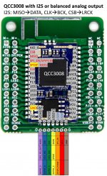
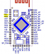
QCC3008 -->I2S -->DAC
Hello Chrome3rus,
have a look at the picture and the links:

Tutorial: LowBudget 4Kanal SureDSP mit DIY-Anteil fürs Autoradio, Projekte der Nutzer - HIFI-FORUM
Connecting a PCM5102a breakout board to a Raspberry Pi – Bjorn's Techblog
Raspberry Pi $4 High Quality Audio – PCM5102A
please tell me how to connect such a PCM5102 to QCC3008
Hello Chrome3rus,
have a look at the picture and the links:
Tutorial: LowBudget 4Kanal SureDSP mit DIY-Anteil fürs Autoradio, Projekte der Nutzer - HIFI-FORUM
Connecting a PCM5102a breakout board to a Raspberry Pi – Bjorn's Techblog
Raspberry Pi $4 High Quality Audio – PCM5102A
Attachments
First of all
Sorry for not being active in this thread for a while. I've had to attend some other matters in between. That's why I also did not answer any personal messages, Sorry for that.Due to popular demand, I decided to create a guide on > how to build your own CSR8675 TWS firmware from scratch < using ADK version 4.1.3.5.
Disclaimer
I do not provide any support for this method, nor will I be responsible for possible bricking of your Hardware. You are completely on your own here. All the statements I make are based on my experience and might not reflect the truth.Build your own CSR8675 TWS firmware from scratch - Part I
Introduction
This guide explains how you can build your own TWS (True wireless stereo) firmware for a CSR8675 using the ADK in version 4.1.3.5. I tested this procedure multiple times and it works for me reliably. This guide also adds AAC and MP3 decoding capabilties, which are not mandatory for TWS, but nice to have.I already build speakers with this functionality included using the same method that I describe here.
I will not go too deep into other topics such as hardware and different scenarios e.g. I²S - there might be other guides on those topics as well.
Prerequisites
- CSR8675 (e.g. BTM-875-B module)
- Your BT module is correctly wired up, has a sufficient power supply, the PWR pin is connected to a button that can switch it to VDD_PADS. This is required to power-up and power-down the BT module.
- Your BT module has a button connected between VDD_PADS and one of the PIO pins (e.g. PIO2) to trigger the TWS pairing once programmed
- You are using a CSR SPI USB adapter or have successfully configured the FTDI variant, I will not explain how to do this here
- You have connected the CSR SPI adapter correct to your BT module
- You have installed ADK Version 4.1.3.5
Prepare project
First of all, go ahead and create a copy of the official sink project that comes with the ADK. You can find that in the apps directory of your ADK installation. In my case, the apps directory can be found at C:\ADK_CSR867x.WIN4.3.1.5\apps .
Give the project a fitting name, based on your liking.

Open project in xIDE
Start xIDE on your machine, I use Windows 10 x64 Professional and it works fine.

After launch you should be greeted with the defaul IDE view displaying the help. For now, we don't really care about any of this. Don't get overwhelmed, we don't need most of this for this excercise.
Navigate to Project and select Open Workspace to get the selection dialoueg.

In that dialogue navigate to the apps directory from earlier. Go into the directory of your custom project (in my case customSink). Select the project speaker from the three available files in that directory.

Hit open to let xIDE load your workspace.
You should now see the IDE in the following state:

The left hand container, called Navigator, contains all the projects in your current workspace.
You can simply collapse the trees of each of the projects to get a better overview of what is loaded in your workspace. Click on [-] for that for each project.
You should now have a nice small list that shows all projects.

At this stage, we have three projects in our workspace:
- vm - 'speaker': The application code for the BT module to be deployed. Includes all logic for the BT module to run, connect etc.
- Kalimba - 'sbc-decoder': The default BT Codec used to connect to your phone.
- kalimba - 'cvc-handsfree': Some noise reduction for headset/microphone use. We could remove it, but I did not bother since I don't use it anyway.
Configure VM project for CSR8675 and TWS
We need to properly configure our project to work on a CSR8675 and with TWS.
For that, navigate to Project and Properties to access the ssettings of the currently active project (vm - 'speaker').

Re-configure the settings as seen in the screenshots:


With that, the speaker project is now correctly configured to work on a CSR8675 later.
Add AAC and MP3 support to your firmware
Now we add the aac and mp3 decoders to your workspace. This allows your BT module later on to use these codecs for audio playback. If you configure a BT module to use AAC or MP3 in the ADK Configuration Tool without the firmware having the decoders compiled into it, your BT module will freeze and crash as soon as you try to start playback.
To add the two decoders to your workspace, navigate to Project and Insert Project into Workspace.
In the selection dialogue, navigate to the kalimba apps directory of your ADK installation. For me it was under C:\ADK_CSR867x.WIN4.3.1.5\kalimba\apps.
In there, open the a2dp_sink directory.
Select the aac_decoder_xip file and hit open.

Perform the same steps again to add the mp3_decoder.xip.

After doing that, you should now have 2 more projects in your current workspace, namely Kalimba - 'aac_decoder' and Kalimba - 'mp3_decoder'.
Build your own CSR8675 TWS firmware from scratch - Part II
Configure decoders for TWS
It is required for us the configure the decoders for TWS use before we can use them. The steps for that are pretty similar and do not require complicated steps. We will have to perform this for the sbc_decoder, aac_decoder and mp3_decoder.
Configuring sbc_decoder for TWS
Right click in the Navigator on the Kalimba - 'sbc_decoder' project. Click on Set as Active Project.

Now right click again in the Navigator on the Kalimba - 'sbc_decoder' project. Click on Properties.

In the properties dialogue, select TWS_WIRED_MODE in the Configuration drop down menu.

Make sure to change the DSP hardware is set to CSR8675/CSR8676.

Hit OK to save the changes.
In the upper navigation bar, select the drop down menu next to Kalimba - 'sbc_decoder' and select TWS_WIRED_MODE.

Now navigate to Build and click Rebuild Active Project.

The output box in the lower part of the IDE should now display output, starting with what you see in the screenshot. After a while, it should prompt Finished.

It is important that the beginning of the output states sbc_decoder.tws_wired_mode.mak. This means that the project is being build with the TWS settings, which is important.
Configuring aac_decoder for TWS
Right click in the Navigator on the Kalimba - 'aac_decoder' project. Click on Set as Active Project.

Now right click again in the Navigator on the Kalimba - 'aac_decoder' project. Click on Properties.

In the properties dialogue, select TWS in the Configuration drop down menu.

Make sure to change the DSP hardware is set to CSR8675/CSR8676.

Hit OK to save the changes.
In the upper navigation bar, select the drop down menu next to Kalimba - 'aac_decoder' and select TWS.

Now navigate to Build and click Rebuild Active Project.

The output box in the lower part of the IDE should now display output, starting with what you see in the screenshot. After a while, it should prompt Finished.

It is important that the beginning of the output states aac_decoder.tws.mak. This means that the project is being build with the TWS settings, which is important.
Configuring mp3_decoder for TWS
Right click in the Navigator on the Kalimba - 'mp3_decoder' project. Click on Set as Active Project.

Now right click again in the Navigator on the Kalimba - 'mp3_decoder' project. Click on Properties.

In the properties dialogue, select TWS in the Configuration drop down menu.

Make sure to change the DSP hardware is set to CSR8675/CSR8676.

Hit OK to save the changes.
In the upper navigation bar, select the drop down menu next to Kalimba - 'mp3_decoder' and select TWS.

Now navigate to Build and click Rebuild Active Project.

The output box in the lower part of the IDE should now display output, starting with what you see in the screenshot. After a while, it should prompt Finished.
Link to screenshot, only 20 inline images allowed.
It is important that the beginning of the output states mp3_decoder.tws.mak. This means that the project is being build with the TWS settings, which is important.
Build your own CSR8675 TWS firmware from scratch - Part III
Enable Codes in Speaker vm
After making sure our codecs build correctly, we need to enable them in the vm - 'speaker' project.
To achieve that, we set the vm - 'speaker' project active by right-clicking onto it in the Navigator and clicking on Set as Active Project.

Now we open the tree of the vm - 'speaker' project and double click on the file speaker.mak to open it in the editor.

Scroll down in the file to find the section of the mp3 and aac decoder includes.

Uncomment the code as seen in the screenshot (remove the leading #) to enable the use of these encoders.

Save the file using CTRL + S.
Navigate to Build and click on Rebuild Active Project to check if your adjustments are correct.

The output in the lower output box should show Finished after a while.

Keep xIDE open!
Erasing flash on BT module
It is important we start from scratch with our BT module, for that purpose, we will delete everything on it. Please make sure to create a complete dump of your module before doing this! MAKE SURE YOU KNOW WHAT YOU ARE DOING!
Open BlueFlash on your machine. Select the SPI adapter from the upper drop down list. Make sure your BT module is powered up.

Click on Stop Processor, other buttons should now not be greyed out anymore.

Click on Flash Erase. In the opening dialogue click on Erase Full Chip. Accept all upcoming prompts.

Flash new Firmware using xIDE
In xIDE go to Debug and click on Transport... (vm - 'speaker').

Select your SPI adaptor in the opening dialogue.

Hit OK do save the changes.
Navigate to Debug and click on Run.

The output box in the lower part of the IDE will display output and should state the following after a while:
Code:
Program the flash with a single XUV file...
.................
Success
Finished.
Initialising execution environment for project 'vm - 'speaker''
Connecting...
Out of memory initialising globals
This is to be expected.
Use PSTool to re-enable BT module
We now have flashed our firmware, but we need to set all default settings using PSTool.If PSTool can't connect to your BT module, power cycle it or use BlueFlash to Stop and Start the Processor.
Start PSTool and select your SPI adaptor. Hit OK to connect.

Navigate to File and click on Merge...

In the opening dialogue, navigate to the configurations directory of your custom project, in my case C:\ADK_CSR867x.WIN4.3.1.5\apps\customSink\configurations
Select the file sink_system_csr8675.psr.

Hit Open and PSTool will apply those settings.
Change your BT Address by changing Bluetooth Address. Make sure you don't have two devices with the same address. Input is HEX.
Click on Set after doing your adjustments.

Change your device name by changing Local device's "user friendly" name to a fitting unique name. Different devices should have different names!
Click on Set after doing your adjustments.

After all that, you can click on Reset & Close
Your BT Module should now be able to start up using the PWR button! Start it to continue with the last configuration steps.
Build your own CSR8675 TWS firmware from scratch - Part IV
Configuring BT module for TWS using ADK Configuration Tool
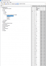
Launch the ADK Configuration Tool, select your SPI Adaptor from the upper drop down menu. Make sure your BT module is powered up!

If the connection was successful, your can click on Go configurable and the Read Device button should become available after some time.

Click on Read Device - the left hand side tree navigation should now become usable.

Navigate to Configuration Set > Bluetooth > BR/EDR Profiles > A2DP and configure the settings as seen in the screenshot.

Navigate to Configuration Set > Bluetooth > Connection Management > Discovery and configure the settings as seen in the screenshot.

Navigate to Configuration Set > Peer Device Support > True Wireless Stereo and configure the settings as seen in the screenshot.

Navigate to Configuration Set > Peer Device Support > True Wireless Stereo > Audio Routing and configure the settings as seen in the screenshot.

Navigate to Configuration Set > User Interfaces > User Events and configure the settings to your liking. My configuration for Peer Session Single Button Pair uses Logical Input 2, Very Long and all conditions except lat last two in the State Mask. VREG and CHG Disabled.

Navigate to Configuration Set > User Interfaces > Buttons > Translation Table and adjust the Logical Inputs to your liking. My configuration sets Logical Input 2 to PIO12.
Click on Write Device and Go Normal. You can now power your BT Module back up using the PWR button.
Your device can now enter TWS Pairing mode if your hold the button on the PIO you have configured for a long time. Do the same on your second device and it will be entering pairing mode as well. After a while, both devices connect to each other and are now working in TWS mode.
Happy Speaker building!
Tell me how to set up qcc3008 so that led2 lights up when the phone is connected to the module and led2 goes out when I turn off the bluetooth on the phone
Please give me Dump file for this configuration..... Please please please please please please please.....TSW with I²C output running!
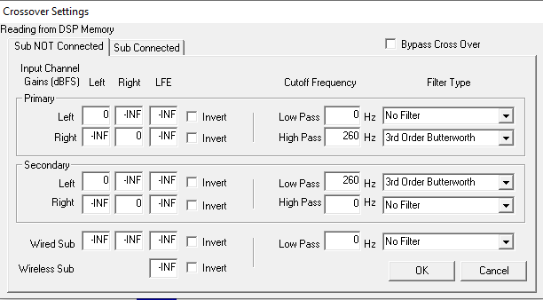
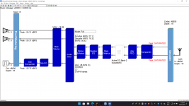
Again progress: I was now able to get TWS + I²S running. Background for that requirement is, that I have more than two speakers and would really love to use the internal DSP and crossover of the CSR8675 for both high/mid speakers and one low speaker.
Since the CSR8675 has two differential outputs, I either needed to do crossover work after the fact (either analogue or with a real DSP like ADAU1701) OR I use I²S to get an additional pair of outputs.
I decided for the latter, since it would really save me footprint and effort. An I²S DAC is cheap to have and the implementation and testing is far more straight forward than designing an analogue crossover (which then would have a fixed dropoff frequency) or implementing a custom ADAU1701 solution.
For the testing I now used a PCM5102A on a generic breakout board. Those can be had for pretty cheap. I scored 5pcs for 25€ on amazon.
The PCM5102A is pretty simple. It does not use I²C for configuration, but rather has some Pins that can influence its mode of operation. Rest is determined by the incoming data from I²S.
I went with the following configuration:
FLT -> low
DEMP -> low
XSMT -> high
FMT -> high
This will automatically have the PCM5102A unmuted and waiting for left-aligned data.
Connection to the CSR8765 is made via dunpont connectors, connecting GND, VCC (3.3V), LRCK/SYNC, DIN and BCK. We don't need SCK for this, so that pin can be left open or tied to ground.
There is some configuration to be done inside the ADK Configuration Tool. I am using Version 4.3.15 with the default sink application.
First of all, we need to enable routing of audio to the I²S output channel:
Next is the specific I²S configuration:
Since the PCM5102A does not have I²C we need to disable all I²C communication, otherwise the CSR8675 gets stuck.
This is done by setting the Number of I²C commands to 0. Also we can configure a ENABLE GPIO which can later be used to automatically soft-mute the DAC via the CSR8675, not using that currently.
Setting that up, the PCM5102A is now appearing in the universal frontend (make sure to have an audio stream running).


sujansnhw@gmail.com
Attachments
Has anybody been able to add custom prompts from a .WAV file for the 8675? Or do you need a custom PCB with external SPI flash memory?
yes, you just have to follow the docs and on screen instructions in ADK config tool. ( i have a random CSR8675 board from aliexpress with just the default 16M flash).Has anybody been able to add custom prompts from a .WAV file for the 8675? Or do you need a custom PCB with external SPI flash memory?
IIRC basically you need to encode your prompt to 8KHz, mono wav, connect with ADK config tool, go to the prompts page, generate the prompt files into the sink application, then rebuild the sink with the prompts (might have to edit the build file so the prompts get included in the image), then build and flash the sink image again.
External SPI memory is not needed for that.Has anybody been able to add custom prompts from a .WAV file for the 8675? Or do you need a custom PCB with external SPI flash memory?
That sounds right to what I remember. The documentation on that is good enough in the offical CSR documents.IIRC basically you need to encode your prompt to 8KHz, mono wav, connect with ADK config tool, go to the prompts page, generate the prompt files into the sink application, then rebuild the sink with the prompts (might have to edit the build file so the prompts get included in the image), then build and flash the sink image again.
I need I2S output for subwoofer. But, I2S board (PCM5102A) not working. please help me......Build your own CSR8675 TWS firmware from scratch - Part IV
Configuring BT module for TWS using ADK Configuration Tool
Launch the ADK Configuration Tool, select your SPI Adaptor from the upper drop down menu. Make sure your BT module is powered up!
If the connection was successful, your can click on Go configurable and the Read Device button should become available after some time.
Click on Read Device - the left hand side tree navigation should now become usable.
Navigate to Configuration Set > Bluetooth > BR/EDR Profiles > A2DP and configure the settings as seen in the screenshot.
Navigate to Configuration Set > Bluetooth > Connection Management > Discovery and configure the settings as seen in the screenshot.
Navigate to Configuration Set > Peer Device Support > True Wireless Stereo and configure the settings as seen in the screenshot.
Navigate to Configuration Set > Peer Device Support > True Wireless Stereo > Audio Routing and configure the settings as seen in the screenshot.
Navigate to Configuration Set > User Interfaces > User Events and configure the settings to your liking. My configuration for Peer Session Single Button Pair uses Logical Input 2, Very Long and all conditions except lat last two in the State Mask. VREG and CHG Disabled.
Navigate to Configuration Set > User Interfaces > Buttons > Translation Table and adjust the Logical Inputs to your liking. My configuration sets Logical Input 2 to PIO12.
Click on Write Device and Go Normal. You can now power your BT Module back up using the PWR button.
Your device can now enter TWS Pairing mode if your hold the button on the PIO you have configured for a long time. Do the same on your second device and it will be entering pairing mode as well. After a while, both devices connect to each other and are now working in TWS mode.
Happy Speaker building!
Attachments
Hi all,
I got some QCC3008 board´s over at Tiny sine(TS3008).
If i establish a Bluetooth connection the connection only lasts 20-70 sec, undependent whether i start to stream over IIS or not. In order to connect to the module again, I need to restart or power up the module. Is this behaviour revered to as “crashing”. If not what could cause be the Problem.
Any input appreciated.
Hi again,
I merged my dump files and checked the connection´s. Apparently i´ve mistaken VCHG with VBAT which seems to have caused the problem.
I´m trying to get the QCC3008 to do some IIS i´m using an FDA903 (Amplifier) which requires the IIS clock to be present in order to execute IIC commands. Apparently one can configure some IIC commands in the ADK software. I took a look at the real datasheet and there is a IIC separate interface but I don’t really know how to use that, or to be more specific. where to program that?
As i understand now IIC is separately transmitted. (not along with the IIS data)
In the ADK software you go Configuration set => Audio => I2S => Raw Command Data:
then there is displayed a list of “random” Numbers. I don’t now what these Numers do or what they mean, or if it is enough to add some specific numbers and my Amplifier starts working.
If anyone knows how the QCC IIC communication works, or could link me to some relevant resources, or has some answers to my question. Is encouraged you to help me out.
Please help me out.
So my next idea would be pretending like my Amplifier wouldn't need IIC to function and input the IIC commands over a separate MCU. Has someone already done that?
Tanks a lot any Input is appreciated, have a nice one
Attachments

OK, just discovered the documentation i needed in case any one else needs it: ADK Support Documentation => Additional Support Documentation => QCC300X I2S User Guide. I apologise fore writing/asking before looking through the entire Dementation. I guess I wanted to go the easy rout again again i´m sorry🙁 Not sure if this brings answers to all my Questions, but in theory it shuld.
HI does anyone here have experience with the QCC51xx series of chips? I have an official ADK toolkit 1.2 installer and it installed assembler, compiler, C compiler (kcc), matlab and python tools, but it didn't come with any sample source code (I have not installed MDE yet and I don't know which version MDE I should be getting). I am doing some research to eventually start writing programs for the 51xx (either 5141 or 5144) series and would like to look at some sample code. I have worked with CSR8675 and it's ADK up to version 4.1
CSR8675 ADK installation came with a sink project, a massive project with the source code with default settings to make the CSR8675 chip work as a bluetooth headset. Can anybody please share the source code for the QCC chip's corresponding sink project? I've looked through this thread and although some members have shared documentation files, I can't find an actual source code to study. I've seen one post that said QCC30xx and QCC51xx are compatible in terms of source code, but I don't have source code for QCC30xx either. Could someone lend a hand please?
Also, if I manage to purchase a 51xx development board from a Qualcomm supplier, will they provide me with installers for the IDE, compilers, source code and other documents? Will they provide all this in a USB? The CSR8675 development board came with an sdcard with all the ADK installers. How does purchasing the QCC equivalent work?
HI does anyone here have experience with the QCC51xx series of chips? I have an official ADK toolkit 1.2 installer and it installed assembler, compiler, C compiler (kcc), matlab and python tools, but it didn't come with any sample source code (I have not installed MDE yet and I don't know which version MDE I should be getting).
Hi,
I have a little bit of experience with it, I am adding different A2DP codecs into it right now (would appreciate some help, algorithmic optimization is required for IMDCT). I have QCC5144 in my hands right now, QCC5151 is going to be delivered soon.
All the source code is on Qualcomm's website.
You will need verified account in order to access it though (and 3000$).
You said that you have ADK 1.2 installer (latest is 1.2.9.25), do you have verified account or you downloaded it somewhere? In second case you will probably find the sources in the same place.
MDE version doesn't matter much, even latest 2.7 crashes in some conditions (i.e. in Debugger when viewing large structures).
All of the QCC514x/5x/7x have the same firmware architecture (there is actually a source code project with support for all of them, it may be found online. PM me if you want a link). 304x/5x/7x series is mostly the same, but it doesn't have programmable DSP (so only what is flashed to ROM on the factory is available, with 5xxx series much more is achievable).
I don't personally manage the verified account but have access to everything that can be downloaded after verificationHi,
I have a little bit of experience with it, I am adding different A2DP codecs into it right now (would appreciate some help, algorithmic optimization is required for IMDCT). I have QCC5144 in my hands right now, QCC5151 is going to be delivered soon.
All the source code is on Qualcomm's website.
You will need verified account in order to access it though (and 3000$).
You said that you have ADK 1.2 installer (latest is 1.2.9.25), do you have verified account or you downloaded it somewhere? In second case you will probably find the sources in the same place.
MDE version doesn't matter much, even latest 2.7 crashes in some conditions (i.e. in Debugger when viewing large structures).
All of the QCC514x/5x/7x have the same firmware architecture (there is actually a source code project with support for all of them, it may be found online. PM me if you want a link). 304x/5x/7x series is mostly the same, but it doesn't have programmable DSP (so only what is flashed to ROM on the factory is available, with 5xxx series much more is achievable).
I think there's two levels of verification with their site; my account was verified the first time after contacting their representative and we were able to download ADK toolkit 1.2.9.25. I don't think there's been any payment at this point
We downloaded the MDE installer as well but I haven't checked it out yet. I have a good guess that's the IDE but haven't confirmed yet. I hope this means my guess was correct.
We were not able to find any source code related to QCC51xx series
When you say source is on the Qualcomm website, do you mean it will only be accessible after we pay for a membership? Previously when we installed ADK for CSR8675 it came with all the sample programs as well. Is that not the case now? We got the ADK software on an sdcard and were allowed access to it's updated versions on the website, when we bought the CSR8675 development board. If we buy a QCC development board will we get similar access, or does Qualcomm do things differently?
Is there something other than ADK toolkit 1.2.9.25 that I need to get started with this? Is "ADK_QCC512X_QCC302X_WIN_6.4.2.26" (or some updated version of this) what I need?
Thanks for the heads up about the 304x/5x/7x chips. I need complete control over the chip's firmware so I guess I will stick with QCC5141 or 5144 if it's available. Do you know what is their difference from the earlier 5121?
Please do share the link to the project that supports QCC514x/5x/7x if it's something you are allowed to share. I'll send you a pm as well.
- Home
- Source & Line
- Digital Line Level
- CSR8675 programming guide w software and tons of CSR info