It's to keep the clocks synchronously. The clock for the lower DAC is stopped certain periods of the Latch, hence the name "stopped clock" method.
Anyway the method with simply inverting the latch for 1 channel sounded slightly better. This was tried with the AD1865 though.
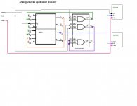
74HC08 is an AND gate, doesn't make sense that the signal and +5vDC are being input into the gate?
Smart?
Yes with two chips AD1865 (balanced DAC) or two AD1851.
😎
Not with a single chip. Both channels share a common serial clock input.
Yes with two chips AD1865 (balanced DAC) or two AD1851.
😎
Not cool enough ?
A real audiophile would have milled off the top of the AD1865 and separated the two channels for a truly valid comparison.
Yes with two chips AD1865 (balanced DAC)
😎
A real audiophile would have milled off the top of the AD1865 and separated the two channels for a truly valid comparison.
A real audiophile would have milled off the top of the AD1865 and separated the two channels for a truly valid comparison.
**
😡
Eureka
Guys I've been messing with this for a while now and could never get it to work
(single inverter) I was was getting a lot of noise in the non inverted channel.
However after some more fiddling last night I had success ,initial listening sounds promising🙂
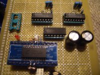
I'm using CS8414 74VHC04 PCM56P
See schema below.
Guys I've been messing with this for a while now and could never get it to work
(single inverter) I was was getting a lot of noise in the non inverted channel.
However after some more fiddling last night I had success ,initial listening sounds promising🙂
I'm using CS8414 74VHC04 PCM56P
See schema below.
Attachments

You can get problems just from the layout of data and clock wires.
Best use passive I/V and analog filter.
Best use passive I/V and analog filter.
Bernhard you have my utmost attention and respect but what do you mean exactly by problems with timing? This sounds awesome the way it is, eg no TDA and no op amps ,
PS data and clock wires are less than 15mm.
PS data and clock wires are less than 15mm.
Last edited:
Bernhard you have my utmost attention and respect but what do you mean exactly by problems with timing? This sounds awesome the way it is, eg no TDA and no op amps ,
PS data and clock wires are less than 15mm.
Longer wires can cause trouble but if you have no problems, all ok 🙂
Film caps for decoupling on all power supply pins would be good.
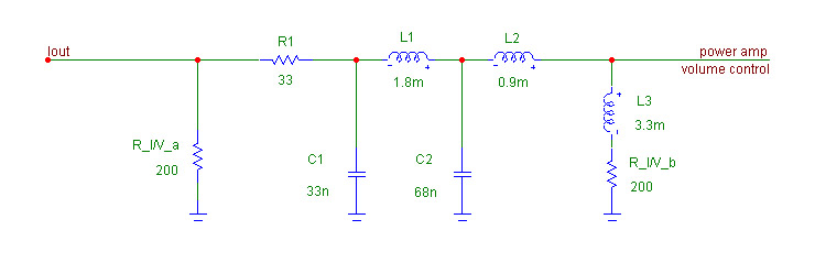
You can try this integrated analog filter: passive I/V + 24 dB lowpass from 20 khz + hf rolloff compensation.
It results in equivalent of 100 ohm passive I/V so you may need some post amplification.
Connect nothing else to Iout.
Sleep
Yep I've been up all night listening to this DAC couldn't stop listening I am talking X factor here and I havn't even started tweaking yet.😱 had to pull away get some sleep
Yep I've been up all night listening to this DAC couldn't stop listening I am talking X factor here and I havn't even started tweaking yet.😱 had to pull away get some sleep
2 X5V
Chips are all decoupled with Millitary grade 100nF glass passivated caps at pins
Only 2 X 5V rails and this little baby is kicking some major ***.
Longer wires can cause trouble but if you have no problems, all ok 🙂
Film caps for decoupling on all power supply pins would be good.
You can try this integrated analog filter: passive I/V + 24 dB lowpass from 20 khz + hf rolloff compensation.
It results in equivalent of 100 ohm passive I/V so you may need some post amplification.
Connect nothing else to Iout.
Chips are all decoupled with Millitary grade 100nF glass passivated caps at pins
Only 2 X 5V rails and this little baby is kicking some major ***.
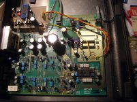
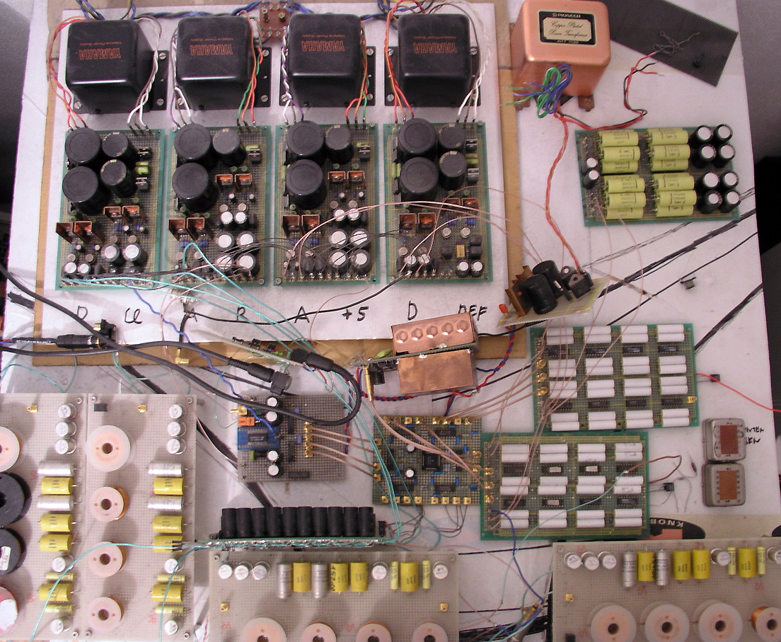
This is my mess with 32 x PCM56:
That looks pretty cool Bernhard. How does it sound? 😱
Too much beer last night just a tad groggy today.
I will try your IV later on if I can find the right chokes in my junk bin.
That looks pretty cool Bernhard. How does it sound? 😱
Too much beer last night just a tad groggy today.
I will try your IV later on if I can find the right chokes in my junk bin.
Its a joke right
Bernhard are you seriously using like 2 amp air coil inductors for your IV?🙁
Who wants to buy some TDA1541As?
Bernhard are you seriously using like 2 amp air coil inductors for your IV?🙁
Who wants to buy some TDA1541As?
I've tried big air coil inductors for dac analog filtering but they always pick up hum, never found a shielded air core. I believed they sounded better but it was tough to say for sure with the hum.
This is my mess with 32 x PCM56:
That looks pretty cool Bernhard. How does it sound? 😱
Too much beer last night just a tad groggy today.
I will try your IV later on if I can find the right chokes in my junk bin.
I'll give it a try:
The sound is so pure and sweet... 🙄
Bernhard are you seriously using like 2 amp air coil inductors for your IV?🙁
Who wants to buy some TDA1541As?
The coils have 0,7 mm wire. That gives low resistive loss.
- Status
- Not open for further replies.
- Home
- Source & Line
- Digital Line Level
- cs8416 + pcm56p