till
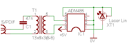
Instead o f XT1 - the input DIR (connect ADM1485 pin 1 to DIR pin 20 DIN)
Do you have any schematic for interconnection of DIR1703 and ADM1485?
Instead o f XT1 - the input DIR (connect ADM1485 pin 1 to DIR pin 20 DIN)
Attachments
Õàëÿâùèê said:till
Instead o f XT1 - the input DIR (connect ADM1485 pin 1 to DIR pin 20 DIN)
Hi Õàëÿâùèê,
Forgive my ignorance,
 but shouldn't the transformer have a centertapped secundary connected to ground as in this picture:
http://www.linear-tech.com/ezone/sinesquare.html

Is your schematic a working circuit?😕
Attachments
Hi, Elso
This ground connection isn`t obligatory, at least ADM works without it. I was not experimented with transformers ground connection, because I use spdif together with a feedback link of synchronization from dac to CD-transport.
If to use single spdif - here there is a place for experiments
Regards
This ground connection isn`t obligatory, at least ADM works without it. I was not experimented with transformers ground connection, because I use spdif together with a feedback link of synchronization from dac to CD-transport.
If to use single spdif - here there is a place for experiments
Regards
Hi, is there a special reason for the ADM chip or would something like SN65LBC176AP http://focus.ti.com/docs/prod/folders/print/sn65lbc176a.html do also? How about the spdif transformers, do you buy them or make them with a small toroid and CuL?
Anyone with experience using isolational amplifiers like ISO150 between reciver and DAC like mentioned in the datasheet: http://focus.ti.com/docs/prod/folders/print/iso150.html
Anyone with experience using isolational amplifiers like ISO150 between reciver and DAC like mentioned in the datasheet: http://focus.ti.com/docs/prod/folders/print/iso150.html
I did not find a crystal oscillator with exactly the right f for 44100Hz for the 1892, so i will use 25MHz.
I recived the DIR1703, and wonder if it will be possible to solder that tiny pins to a socket...
The CS8412 does detect very much better when spdif cable is plugged in/off than the AD1892. The AD does sometimes not detect spdif away and make digital noise.
I recived the DIR1703, and wonder if it will be possible to solder that tiny pins to a socket...
The CS8412 does detect very much better when spdif cable is plugged in/off than the AD1892. The AD does sometimes not detect spdif away and make digital noise.
Try!
Hi Till, Just try it and see or listen hat happens.😉
till said:hmm, seems there is no interest in that chip.
should i use 25Mhz; 23,40 MHz or 24,00 MHz ?
Hi Till, Just try it and see or listen hat happens.😉
DIY
Juat make the oscillators on a separate boards or make them on a socket that you can connect to the AD chip at will...........

Oh No, don't do this to me.till said:so i have to order 3 instead of one
Juat make the oscillators on a separate boards or make them on a socket that you can connect to the AD chip at will...........

i have a socket DIL14 next to the AD1892, at the monent a 25,175MHz QXO with 4 pins out of an old VGA card plugged into.
AD1892
//if this post is not too late 4 u//
I use AD1892 w. 24.576Mhz clock, i.e. it is resampling up to 48kHz. No problems when switching on/off the digital input - there are digital amps and diy transformers on the coax inputs, w. 74HC04 /low cost 😉)/ Btw things were worse with the previos revision of the input amplifiers /74hc04/ - I'd added some resistors/caps to eliminate the problem.
The dac is AD1852, with OPA2134 analog stage.
This dac has outperformed every CD/DAC it was compared to /in the class up to $600-2000/, the clock is something like Elso's /Thanks Elso for the schematic/, but not exactly the same 😉)
I am considering the "bad sound of this 1892 device, due to its internal digital filter", next project will be w/o 1892.
//U can go ahead with 25Mhz clock, but if more 1892 may not operate. Do it externally, like Elso suggests, and you will be able to use his fine clock circuit some day, if not from the beginning//
[off]
Õàëÿâùèê
Where you were lost?!
I shall be glad to see at Konkere!
(or I don't learned You?)
[/off]
Õàëÿâùèê
Where you were lost?!
I shall be glad to see at Konkere!
(or I don't learned You?)
An externally hosted image should be here but it was not working when we last tested it.
[/off]
AD1892 uses a DPLL for input data recovery and consequently when it is used in ASRC bypass mode, it's jitter performance will be quite horrible. Bypass mode is used to pass-through non PCM data like AC3 coded streams, it should not be used for audio.
Inherently AD1892 has no jitter performance - it is up to the DAC chip connected to it to reclock the data properly, but as far as I know, all of them do that anyway. The input clock on the AD1892 is specified by duty cycle, which can be 50%+-10% - in terms of jitter this is a huge value. Internal ASRC rate estimators have a very long time constant to this high clock jitter will not affect correct ASRC performance.
The AD1892 is primairly designed for redbook spec SPDIF, i.e. 16-bit input. Because it is indeed a form of a digital filter (just like any ASRC) it's output must have a higher resolution to prevent excessive rounding errors. If it is used with a DAC that has less than the full 20-bit resolution, the actual resolution with respect to the input will be LOWER as there will be substantial distortion due to quantization nosie (if the output 20 bits are just truncated to 18 or 16), or there will be about 0.5-1 bit loss due to dithering into 18 or 16 bits if the appropriate mode is selected in the AD1892 via external CPU.
The same resolution loss exists in all systems where digital filtering is used without expansion of the output data word width WRT the input data word width, and is also one reason why non-oversampled 16-bit DACs gain in resoultion compared to the same DAC being used with oversampling. To make things worse, digital filters that do not expand the output data word width tend to be very old designs that do not perform at the level of it's DAC contemporaries.
In other words, for a stand-alone application use a DAC capable of 20 or more bit input to get good results - using a 16-bit or 18-bit DAC will have rather bad results unless the AD1892 is set to the appropriate output word length via CPU control.
When using the AD1892, be sure to always up-sample the input. The AD1892 does not have bandwidth limiting when down-sampling, so for instance when 48kHz input is downsampled to 44.1kHz, the top 3.9kHz over 44.1kHz Fs, wil alias under 44.1kHz Fs. The maximum guaranteed clock for the AD1892 is 25MHz, corresponding to a sampling rate of 48.828k approximately. However, it seems to work just fine with a slightly higher clock, 27MHz worked just fine on all the parts I had. Using a slightly higher power supply voltage than the nominal 5V (like 5.1 or 5.2V) may help if you want to get the maximum out of it.
- Status
- Not open for further replies.
- Home
- Source & Line
- Digital Source
- CS8412 or AD1892?

