What is interesting is that if he just creates the sound file with level steps at zero crossing, and runs that through his system without a PGA in the chain, he also hears clicks!
Don't know any details but it seems to indicate it''s not a reset or mute issue.
Jan
Don't know any details but it seems to indicate it''s not a reset or mute issue.
Jan
Exactly!What is interesting is that if he just creates the sound file with level steps at zero crossing, and runs that through his system without a PGA in the chain, he also hears clicks!
Don't know any details but it seems to indicate it''s not a reset or mute issue.
Jan
As said if you want me to send you my audio file and you can hear it your self.
Exactly!
As said if you want me to send you my audio file and you can hear it your self.
No thanks; I think you already decided that either my ears or my speakers are bad 😎
Jan
Dear Jan i didnt ment to offend you in any way, if thats the case im sorry.No thanks; I think you already decided that either my ears or my speakers are bad ��
Jan
My ears are very very sensitive to any noise that shouldn't be where its not supposed to be, this is the outcome of many years of studio time, making music, mix and mastering.
Maybe im missing something in the sync between the mute and the cs?
Maybe there is a delay of the mute operation when the cs is working, i dont really know.
As i read what Brian said it gives me hope in some sort.
Maybe really when there is click of volume change the mute suppose to work and this is kind of zero crossing?
This is why i asked what is the mute code line command.
Last edited:
No I am not offended, but a little logic tells me there may not be any problem with the PGA if you also hear it without it. Or you focus on the PGA control and decide that the test with the created file is not valid. Then the question is why not. This is a very important question.
You won't get anywhere just switching between solutions, like the guy looking for his car keys under the street lamp.
Jan
You won't get anywhere just switching between solutions, like the guy looking for his car keys under the street lamp.
Jan
In the audio file i made i can control the change exactly at the zero cross but i cant illustrat the cs or mute function of how they are working together.
Maybe its the combination of the two that makes the zero cross work?
Maybe its the combination of the two that makes the zero cross work?
It is not really important here how the zero crossing works in detail. If you are sure you have a file with good zero crossing and it gives clicks on your system, why?
BTW if you simulate a stepped sound file, be sure to make it band-limited to avoid very sharp transistions at the zero crosings.
Jan
BTW if you simulate a stepped sound file, be sure to make it band-limited to avoid very sharp transistions at the zero crosings.
Jan
Last edited:
Yes your right.
There is no way i should get clicks at zero cross, no matter what.
What we see and what we hear are totally different things.
I think that its the timing issue.
Meaning ....if you move your hand in the air fast enough, say in 50Hz speed you will hear it, see where im getting to with this?
If the sine wave is 500Hz and the changes at 20ms the pass is very fast even at zero crossing we will hear clicks cause the pass are sonic speed
Last edited:
BTW if you simulate a stepped sound file, be sure to make it band-limited to avoid very sharp transistions at the zero crosings.
Jan
Band limited?
I did the audio using only 500Hz
Or you mean something else?
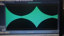
I attached the audio file pic, you can see the steps
As it goes high in volume the steps are more significant same goes for the clicks.
This is how exactly it looks and sounds from the output of the PGA2310
Attachments
Last edited:
I copied that from pga2311 on page 7.
I have never used the part(s) enough to confirm your findings. All I have done so far is wire up a proto following the old Elektor hi-end pre-amp article and I wired it up on another proto to test out my xmega code. I just used sine waves to test, without actually running audio through them.
Something for me to investigate, since you are not the first I have heard having problems with this part.
I suggest to prototype with the intention of trying out all of the varieties to see if they perform the same. It is possible that they do not behave the same.
Ok guys, now i think its final.
I just finished playing with the PGA2310 - EVM
The clicks are still there and will be there forever.
My final request will be from Brian, please record your clicks free PGA2310 output, i wanna hear it very much.
I just finished playing with the PGA2310 - EVM
The clicks are still there and will be there forever.
My final request will be from Brian, please record your clicks free PGA2310 output, i wanna hear it very much.
Hi linuxworks
Do you have tips about the CS3318?
In/out buffers, dc block caps and so...
I have 5 units just in case one will burn.
This chip have a great resolution 1/4 dB for step will do yhe trick i think (and hope).
Do you have tips about the CS3318?
In/out buffers, dc block caps and so...
I have 5 units just in case one will burn.
This chip have a great resolution 1/4 dB for step will do yhe trick i think (and hope).
Band limited?
I did the audio using only 500Hz
Or you mean something else?
Yes I did mean something else. You can switch levels at zero crossing but you can still have very sharp changes at that point, as I described earlier. It is as if you modulate the signal with a square wave.
So you must band-limit the total signal to say 20kHz to smoothing the changes at the zero crossing otherwise you will have the sharp transitions cause short pulses at the switching rate. Possibly you hear that.
A simple experiment would be to run your artificial signal through a (software) 20kHz low pass and see if that changes the sound.
Jan
Hi Jan.
Thanks for the input.
At first i thought like you, exactly the same.
But when i turn the encoder to have one step, only one step and hear this one step, this theory was over.
Unless you think otherwise?
The second test i did was connecting pin 15 (AGND) to GND via 30k resistor to increase the resolution, and from the output of R to the input of L, from the output of L to the studio monitor.
In addition Some changes in the code.
The clicks are totally gone.
this solution is like touching your left ear with your right hand.
Hi linuxworks
Do you have tips about the CS3318?
In/out buffers, dc block caps and so...
I have 5 units just in case one will burn.
This chip have a great resolution 1/4 dB for step will do yhe trick i think (and hope).
it does go down to 1/4 db but that's a strange thing. half db is almost too fine to be useful (my code supports half db changes but I prefer to just show whole db and count in whole db).
the user interface also suffers if you use .25db steps. you now need TWO digits after the dot to show the db value. for many displays, that's wasteful and 'noisy' (visual noise that really is not useful to the user).
I used opto couplers to level shift the 5v from arduino to the 3.3v needed for the 3318. optos are usually slow so I bitbanged the spi in software and that worked ok, but I would probably do it differently today.
there is an 'errata' that MUST be loaded at startup time. I can look for the init strings if you can't find them. I don't think there is such a thing for the pga but there is for the cirrus chip.
the cirrus is also an odd voltage on output. its 8 or 9v, which isn't the full 12 or 15v that people have come to expect (pga can run 15v rails) and also its not dual 5v, so you can't just use a simple 5v psu for it.
I have not given up on the chip, but I have turned my focus to the cheaper and easier pga chips, at least for now. the cost of the 3318 chip is so high, it hurts a lot when you burn the chip. with pga, a $5 burned chip is no big deal.
also be careful about sending a signal (by mistake) to the OUTPUT of the 3318. I blew up my chip by reversing in and out one late nite and that taught me the lesson of WHY output buffering (with op amps) is such a good idea for chips like this.
in my case the CS3318 will be cheaper from the PGA.it does go down to 1/4 db but that's a strange thing. half db is almost too fine to be useful (my code supports half db changes but I prefer to just show whole db and count in whole db).
the user interface also suffers if you use .25db steps. you now need TWO digits after the dot to show the db value. for many displays, that's wasteful and 'noisy' (visual noise that really is not useful to the user).
I used opto couplers to level shift the 5v from arduino to the 3.3v needed for the 3318. optos are usually slow so I bitbanged the spi in software and that worked ok, but I would probably do it differently today.
there is an 'errata' that MUST be loaded at startup time. I can look for the init strings if you can't find them. I don't think there is such a thing for the pga but there is for the cirrus chip.
the cirrus is also an odd voltage on output. its 8 or 9v, which isn't the full 12 or 15v that people have come to expect (pga can run 15v rails) and also its not dual 5v, so you can't just use a simple 5v psu for it.
I have not given up on the chip, but I have turned my focus to the cheaper and easier pga chips, at least for now. the cost of the 3318 chip is so high, it hurts a lot when you burn the chip. with pga, a $5 burned chip is no big deal.
also be careful about sending a signal (by mistake) to the OUTPUT of the 3318. I blew up my chip by reversing in and out one late nite and that taught me the lesson of WHY output buffering (with op amps) is such a good idea for chips like this.
i'm with 7.1 channels balanced and each PGA cost 20$, this means that i need 8 units.
the CS3318 i'll need only 2, it will be chipper.
i'll gonna use opa2134 as input buffer and the ne5532 as ouput buffers
they both can run with (+)(-)9V, so i think i'm cool here.
i'll be using arduino, the arduino outputs 3.3V.
Hi linuxworks and jan.didden, how are you friends? 🙂
i'm in the middle of design the board to the CS3318, i'm going the etching way.
i was looking on some of the designs online and i sew some sort of IC instead of pull ups/down resistors.
meaning in the digital part (MOSI,CLOCK etc..)
i wanted your advice here.
how should i connect those pins to Arduino, pull ups/downs, special isolator IC...?
RESET - ?
MUTE - ?
SCL/CCLK - ?
MOSI - ?
CS - ?
i thank you for your help guys.
cheers and SHABAT SHALOM
Isak
what I used was SPI (the chip comes up by default, IIRC, in spi mode and not i2c mode) and spi lets me get away with opto couplers. they can be set to be a level converter and they also isolate the cpu from the preamp chip (if you care about such things). note that you have to be aware of the speed you want to run spi at and make sure the opto is fast enough. my first try, I used cheap optos and they were too slow. I then bought much faster ones (10x speed faster, or more) and that was enough.
I never tried i2c on that chip. the spi solution worked fine for me. if you have a native 3.3v controller, then you can directly drive the chip (with some small series R's, which is typical).
I never tried i2c on that chip. the spi solution worked fine for me. if you have a native 3.3v controller, then you can directly drive the chip (with some small series R's, which is typical).
thanks for replying linuxworks
i'll be using SPI.
my question is ..do i really need/must use it, cant i just use pull up/down resistors?
my other question is, i know the CS3318 works on 3.3V, i know the arduino clock, miso, CS... are all 5V
is it ok for me to use it directly from arduino to the CS318 or this is the reason i need the "Level Converter"?
BTW, i'll be using the 9V rail to get my 3.3V using this device...
10 PCS LM2596 DC-DC buck adjustable step-down Power Supply Converter module | eBay
hope its ok and stable enough.
- Home
- Source & Line
- Analog Line Level
- cs3318 and arduino