The original CrystalFET.
The original worked, and sounded nice, but suffered from a couple of issues:
1. At MC gain, the circuit ran flat out, with no degeneration (feedback) on the source of the JFET amplifiers. The circuit gain was completely dependent on carefully matching the J113 devices, and finding two with enough gain was very, very hard.
2. The circuit has negative PSRR. It literally amplifiers the B+ signal on the output. (negative PSRR!). That meant the power supply had to do all the heavy lifting to reduce ripple and noise to vanishingly small levels.
At first, my followup was just going to remove the MC gain configuration and be MM only. On further consideration, however, it seemed sensible to adopt the feedback RIAA topology often seen on the old 12AX7 tube preamp designs, to at least some ripple rejection and make the whole thing a little less dependent on having matched devices.
A recent email I got inquiring after the CrystalFET prompted me to have another look at the problem. After a bit of messing around, this is the result.
[design idea, untested, for comment]
Attachments
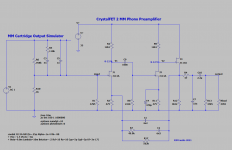
Since MM cartridges are basically inductors, I suspect that block described as an "MM cartridge output simulator" is actually an inverse RIAA network with an output impedance of 1k ? Not quite the same thing.
The lack of inductance is probably not an issue for the JFET with its very low current noise (with a BJT circuit it would strongly misrepresent the current noise importance). I'm not sure of the current noise for a 12AX7, hopefullly its very low too.
MC outputs require ultra-low voltage noise input stages, MM require low current noise, so typically one amp cannot do both well. With valve circuitry its commonly chosen to use a transformer to boost MC input levels and impedance.
There's the 0.5838 pA/sqrt(Hz) current noise from R1, the current noise of the JFET or 12AX7 should be negligible compared to that as long as the gate is not driven into forward conduction/grid is sufficiently negative with respect to the cathode and as long as the JFET's drain-source voltage is not so high that you get much increased gate current due to impact ionization.
Last edited:
The front end is just quick-and-dirty to get the inverted RIAA response. JFETs are low current noise devices, and I'm anyway not out to simulate noise performance here.
The bigger concern is I realized the PSRR is not improved any when moving from the passive RIAA network to the active one. It's a "six of one, half dozen of the other" thing. So there isn't a lot of point as far as I can see. The feedback should reduce distortion I guess, but that's about the only useful function it serves.
The bigger concern is I realized the PSRR is not improved any when moving from the passive RIAA network to the active one. It's a "six of one, half dozen of the other" thing. So there isn't a lot of point as far as I can see. The feedback should reduce distortion I guess, but that's about the only useful function it serves.
You are right about the PSRR, I think, because the transformation from current injected into the first drain back to the input doesn't change. You could of course change the first drain resistor into an RCR circuit to filter off supply ripple, or use some sort of current source.
The feedback does reduce the impact that Miller effect has on the input impedance.
The feedback does reduce the impact that Miller effect has on the input impedance.
Replacing the drain resistors with CCS should be the answer I guess. Though I was able to get a quiet output in the original, even running as a MC phono stage. It just took crazy efforts on the voltage regulation side to get there.
Don't use a PTAT current source like the LM334 or a bandgap current source, they are usually very noisy.
- Home
- Source & Line
- Analogue Source
- CrystalFET 2 (MM) : J113 design idea