The idea to use salvaged ATX PSU for heater and B+ pops up once in a while and the answer is usually that the main transformer has to be re-wound which is difficult especially for higher voltages.
Looking at the schematics (a collection can be found at AT and ATX PC computer supplies schematics) I wonder whether it might be feasable to leave the ATX PSU as is, load the 12v rail with tube heaters and just connect an additional similar transformer to the AC output of the one already in place - albeit IN REVERSE.
Would that give me the desired 300 volts or so - after rectification and filtering of course ?
Or would this play havoc with the PSU if I tried ... ?
Regulation might be poor w/o further modifications but still ...
take B+ from PFC output. That should be around 350-400VDC.
Then take heater from 12v or modify feedback so 5v becomes 6.3v
Then take heater from 12v or modify feedback so 5v becomes 6.3v
powerflux,
is there any isolation, if he would do so?
Without isolation is very dangerous!
Payloads idea of using another trafo should work.
is there any isolation, if he would do so?
Without isolation is very dangerous!
Payloads idea of using another trafo should work.
most of the PFC's used in ATX power supplies are isolated. However, you can't be too sure. Always check, never trust the internet.
most of the PFC's used in ATX power supplies are isolated. However, you can't be too sure.
Hi,
I'm quite sure that PFC's in general are not isolated. Usual topology is a rectifier bridge connected directly to the mains, at it's best via a NTC, then followed by the PFC arrangement which provides a raw DC voltage of ~400 volts for the switching devices.
Best regards!
Edit: The idea of rewinding the isolation tranny probably tends to fail due to the brittleness of the core ferrite. I've never managed to dismantle such a xformer yet.
Last edited:
Excuse me. You are absolutely right. My statement was based on that the secondary does float.
see, never trust the internet 😉
see, never trust the internet 😉
PFC out is certainly on the mains input side and I do not want to touch that at all.
Actually the entire ATX PSU would stay as is, the B+ trafo being just add-on.
I measured one of the salvaged transformers for inductance and came up with 4mH on the primary and 60uH center tapped for 12v secondary (170uH for 5v).
This is about consistent with what I found here: http://danyk.cz/s_atx01u.png.
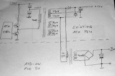
Assuming I connected an identical transformer backwards like in the attached drawing I should be back to 300v ... or maybe not ?
The turns ratio is sqrt(4000uH/60uH) = 8 which may not be enough.
This is why I connect across the center tap of the 12v output.
Before I try that I would appreciate some opinion whether it is worth doing and whether there might be any adverse effects on the PSU itself ?
Actually the entire ATX PSU would stay as is, the B+ trafo being just add-on.
I measured one of the salvaged transformers for inductance and came up with 4mH on the primary and 60uH center tapped for 12v secondary (170uH for 5v).
This is about consistent with what I found here: http://danyk.cz/s_atx01u.png.
Assuming I connected an identical transformer backwards like in the attached drawing I should be back to 300v ... or maybe not ?
The turns ratio is sqrt(4000uH/60uH) = 8 which may not be enough.
This is why I connect across the center tap of the 12v output.
Before I try that I would appreciate some opinion whether it is worth doing and whether there might be any adverse effects on the PSU itself ?
Attachments
Please don't forget the half bridge configuration of the primary side of the power transformer. This means that the voltage across it is, at it's best, 300 Vpp! So you'll need a voltage doubler.
Best regards!
Best regards!
Please don't forget the half bridge configuration of the primary side of the power transformer. This means that the voltage across it is, at it's best, 300 Vpp! So you'll need a voltage doubler.
Best regards!
I didn't. Thats why I connected the additional trafo across both halves of the original center tapped.
4mH -> 120uH (60+60) -> 60uH -> 4mH . I guess thats a doubler in winding ratios already. Actually I would be happy with 250v.
Did the experiment today - it works ! surprisingly well !
355 V @ 225 mA / 80 W when hooked up to the 12V AC rail
and regulation is not poor either, 366v @ 150mA, 380v @ 75mA
other voltages are also possible, 250v on the 5V rail, 200v on the 3.3v rail
I'd call that a success ... 🙂
Another good thing: the B+ can be floating and who says I cannot hook up 4 transformers for the 4 floating PSs for a classic circlotron 😉
Attachments

this sounds like a recommendation to direct link to mains Live.take B+ from PFC output. That should be around 350-400VDC.
Then take heater from 12v or modify feedback so 5v becomes 6.3v
This discussion is banned on this Forum.
this sounds like a recommendation to direct link to mains Live.
This discussion is banned on this Forum.
agreed, and we already ruled that out right away;
the main part of the discussion is NOT about direct linking to mains Live ...
So, without even touching the primary side of the PSU this simple add-on to the secondary side works ! surprisingly well !
355 V @ 225 mA / 80 W when hooked up to the 12V AC rail
and regulation is not so poor as I expected either, 366v @ 150mA, 380v @ 75mA
other voltages are also possible, 250v on the 5V rail, 200v on the 3.3v rail
I'd call that a success ... 🙂
Add-on to produce B+ voltage for tube from PC ATX PSU secondary
there were a couple of small problems which are fixed now, I think
my target is more like 250V and there was unnecessary heat produced in trafo and diodes
Preliminary final status:
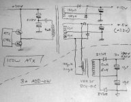
- additional transformer hooked up to 5V secondary AC rail now
- used more of the windings available on the additional trafo
- which requires simple 2-diode doubler to get the target voltage
- tested with two slightly different trafos
- both run simultaneously currently producing 275v and 265v at 120mA each (65W total)
two words of caution though:
although this method is only dealing with the secondary isolated part of the PSU there are life parts in the box which must not be touched nor modified !
the temperature sensor for the PSU fan is usually attached to the heat spreader of the rectifiers which are the hottest spot under normal use; since the power for the add-on is taken from the secondary AC side of the PSU, it does not run thru these rectifier diodes; they stay cold therefore; the power switch transistors however do get hot depending on power drawn but they usually don't have a sensor; which means that the fan speed would not be adequate to sufficiently cool the switches; because the switches are on the mains life side, one cannot safely move the sensors to the heat spreader of these switchers;
so it is required to find a better albeit safe place for the sensor or wire the fan directly to the 12v rail so that it stays permanently on !
there were a couple of small problems which are fixed now, I think
my target is more like 250V and there was unnecessary heat produced in trafo and diodes
Preliminary final status:
- additional transformer hooked up to 5V secondary AC rail now
- used more of the windings available on the additional trafo
- which requires simple 2-diode doubler to get the target voltage
- tested with two slightly different trafos
- both run simultaneously currently producing 275v and 265v at 120mA each (65W total)
two words of caution though:
although this method is only dealing with the secondary isolated part of the PSU there are life parts in the box which must not be touched nor modified !
the temperature sensor for the PSU fan is usually attached to the heat spreader of the rectifiers which are the hottest spot under normal use; since the power for the add-on is taken from the secondary AC side of the PSU, it does not run thru these rectifier diodes; they stay cold therefore; the power switch transistors however do get hot depending on power drawn but they usually don't have a sensor; which means that the fan speed would not be adequate to sufficiently cool the switches; because the switches are on the mains life side, one cannot safely move the sensors to the heat spreader of these switchers;
so it is required to find a better albeit safe place for the sensor or wire the fan directly to the 12v rail so that it stays permanently on !
Attachments
I'm a bit of a tube nerd. I have been wondering about something like this. But I did not want to wind my own for a host of reasons. The re-use of the existing transformer backwards is just brilliant!
This is too cool. I have to try it! Thanks.
-ASC
This is too cool. I have to try it! Thanks.
-ASC
Thanks
That's pretty cool man. Thanks for posting. I'm going to try to make one of these. Now that I finally have a box of ATX supplies in the garage that is. 🙂
-ASC
That's pretty cool man. Thanks for posting. I'm going to try to make one of these. Now that I finally have a box of ATX supplies in the garage that is. 🙂
-ASC
- Status
- Not open for further replies.
- Home
- Amplifiers
- Power Supplies
- Crude idea to modify PC ATX PSU for Tube Amp